I would also disconnect the can connections from the output, they should be connected to the chassis. The shell of the RCAs is ground in your preamp but not in the Dac, the output is purely differentially balanced. Remember, you are using input trafos as output trafos, and you must keep your interconnects shorter than about 1.5m.
I have about 100 other things to try, they keep popping into my little pea brain.
I have about 100 other things to try, they keep popping into my little pea brain.
Last edited:
I'm using the Jensen transformers and I didn't notice a drop in the bass though I didn't measure it.
Would it be possible for you to do some measurements? 😛
Did you take the measurements without any load connected? I would try a 20k load resistor. Everything I have read about high impedance trafos says you need a load.
Actually I had the 510r series+10nf parallel on the primaries with this measurement. I did re-measure with 220r in series, and without any load. Unfortunately, the results are the same. Do you mean I should try 20k in parallel with the primaries? 🙁
On the primary side I have 249 ohms in series and a 2.2nF cap across the inputs. My secondary is the same as yours.
Im just waiting for my order of 2.2nf and 1nf wima caps from Romania. I have only 220r resistors to try. do you think it would suffice?
Try snipping your links at the cap positions, you can always reconnect them with a drop of solder.
Thats the first thing that I will do when I get home...
I would also disconnect the can connections from the output, they should be connected to the chassis.
Bill, do you mean the white and black wire? I tried connecting the white wire to the chassis yesterday but got the same results. I will try grounding the black and white wires to the chasis.
The Jensen transformers are interesting to me. If you are thinking of dumping them, I might be interested in buying them if the price was right.
Just wait for some time Sheldon, since I might be doing it ... 🙂
You can do anything you want on the primaries, I was talking about the secondaries. Place 20k right across the RCAs.
I think the white is the can and black is internal shield, you can probably abandon both with no ill effect. The can connection could be pulling one phase to ground if bolted to a grounded chassis.
I think the white is the can and black is internal shield, you can probably abandon both with no ill effect. The can connection could be pulling one phase to ground if bolted to a grounded chassis.
Need to go and find me some 20k resistors.. will also try removing the can and shield connections..
Thanks Bill..
Thanks Bill..
Hi Ryssen, thanks for the post. One thing is bothering me, though. Sorry for such a question, but are you sure that pinout of MJE350 is correct (i mean reversed legs, CEB)? From what Salas said "Where gate=base, drain=collector, source=emitter" i would suppose that if IRFP9240 pinout was GDS, then MJE350 pinout would be BCE, which means that whole case must be reversed when mounting on our board, no need to reverse legs. Could you please check it? I may be wrong of course, i'm no expert in any way. 🙂
Thanks,
Fred
Thanks,
Fred
Need to go and find me some 20k resistors.. will also try removing the can and shield connections..
Thanks Bill..
Number one thing to try is still clipping the links, I suppose.
Hi Ryssen, thanks for the post. One thing is bothering me, though. Sorry for such a question, but are you sure that pinout of MJE350 is correct (i mean reversed legs, CEB)? From what Salas said "Where gate=base, drain=collector, source=emitter" i would suppose that if IRFP9240 pinout was GDS, then MJE350 pinout would be BCE, which means that whole case must be reversed when mounting on our board, no need to reverse legs. Could you please check it? I may be wrong of course, i'm no expert in any way. 🙂
Thanks,
Fred
I think you are right about that..😱 But it´s leaving 3,3v out..
I will switch the 2 legs emitter and collector and see how it works.
The base is right connected.
Hi Bill, just bought the 20k resistors and replaced the 13k on the secondary leaving the 620pf cap intact. Powered up and tested... still no change. Next thing i did was to remove the links on the caps then remove the 12 volt supply, did another test... still the same. Last thing I did was to isolate the can and internal shield but got no improvement whatsoever. I'm beginning to think that this is the normal response of the trafo with this dac. One thing I haven't tried is the 2.2nf capacitor across the primaries coupled with 220r resistors in series. I'm listening to the dac right now and there's adequate bass from 20hz onwards. The midrange and treble response are great. Thank you for your patience.. Sonny
Ok,now i connected MJE350 the right way..that you described it.I think you are right about that..😱 But it´s leaving 3,3v out..
I will switch the 2 legs emitter and collector and see how it works.
The base is right connected.
And it works,gives 3,3v..Thanks for telling me about it! 🙂
Just want to pop in and say I am enjoying the AD1865 DAC from rainbow_hui.
I did some of Lukasz 'lampizator' mods (just to the board, not the actual lampization) and it sounds really, really good. A little dark, rolled off is my only issue. Midrange is very natural. Textured. Nina Simone sounds fantastic. Very different from my gigawork/transformer to my ears. I am going to compare the two over the coming weeks as I tweak it. Not really fair to compare right now as my gigawork has premium parts like shinkoh resistors REL polystyrene caps, etc.
Definitely sounds better than the gigawork w/ opamps.😎
Attachments
New Version
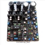
I just got my copy of this DAC in the mail today. Gigawork apparently has a new version of this unit. The power supply caps seem to be larger, the diodes appear to be different, and most importantly the op-amps are now pairs of OPA627's on adapter boards. A lot of the analog stage seems to have been streamlined as well. Here's a couple pictures:


Sheldon
I just got my copy of this DAC in the mail today. Gigawork apparently has a new version of this unit. The power supply caps seem to be larger, the diodes appear to be different, and most importantly the op-amps are now pairs of OPA627's on adapter boards. A lot of the analog stage seems to have been streamlined as well. Here's a couple pictures:
Sheldon
Ok,now i connected MJE350 the right way..that you described it.
And it works,gives 3,3v..Thanks for telling me about it! 🙂
You're welcome 🙂 Glad that it worked for you. I just measured voltage between collector and emitter, and it is 3.3v, which means that transistor is working (i think 🙂). As for why it was working the first time - if you'll look at the schematics, it's actually first MOSFET doing all the dirty work, second MOSFET is just to soften what's left from first. So, even without second transistor, board will still give out 3.3v (or whatever is set via trim pot). Again, that's just my thougths, we better ask Salas how exactly it works 🙂 But that's outside of current topic, of course.
Hi Bill, just bought the 20k resistors and replaced the 13k on the secondary leaving the 620pf cap intact. Powered up and tested... still no change. Next thing i did was to remove the links on the caps then remove the 12 volt supply, did another test... still the same. Last thing I did was to isolate the can and internal shield but got no improvement whatsoever. I'm beginning to think that this is the normal response of the trafo with this dac. One thing I haven't tried is the 2.2nf capacitor across the primaries coupled with 220r resistors in series. I'm listening to the dac right now and there's adequate bass from 20hz onwards. The midrange and treble response are great. Thank you for your patience.. Sonny
Hi Bill, sorry for I misunderstood your instructions. Now I have tried connecting the 20k resistors across the secondaries. Also tried different values. Finally got a flat response from 10hz, dropping only by 1db from 10khz, by placing a 15k resistor on the positive of the secondaries. Is this response ok? Could we further improve on the treble response? Right now im happy of the results... Thank you so much to all who helped specially to you Bill.. 🙂


Hmm.the OPA627 is a single opamp,have they made a channge in the schema?the op-amps are now pairs of OPA627's on adapter boards. A lot of the analog stage seems to have been streamlined as well. Here's a couple pictures:
The first transistor is the current source,that sets the current,the second is the shunt element,that shunts to earth,and should set the voltage,why it worked with the transistor backwards i don´t know...😕As for why it was working the first time - if you'll look at the schematics, it's actually first MOSFET doing all the dirty work, second MOSFET is just to soften what's left from first.
Hmm.the OPA627 is a single opamp,have they made a channge in the schema?
Nope, you misread my description (Or I didn't make it obvious). There is a PAIR of OPA627's on each adapter board. You only see one, the other is tucked underneath.
Sheldon
I think its just a mistake from Gigawork since they haven't changed their description and pricing.
so at the end what is better OPA627 or transfo?
CS4398 or PCM1793 ?
CS8416 or DIR2009?
to much option to take a décision..
CS4398 or PCM1793 ?
CS8416 or DIR2009?
to much option to take a décision..
Last edited:
Hi Bill, sorry for I misunderstood your instructions. Now I have tried connecting the 20k resistors across the secondaries. Also tried different values. Finally got a flat response from 10hz, dropping only by 1db from 10khz, by placing a 15k resistor on the positive of the secondaries. Is this response ok? Could we further improve on the treble response? Right now im happy of the results... Thank you so much to all who helped specially to you Bill.. 🙂
A 1db hiccup could be from anything, I would listen and not worry about it. Enjoy.
Finally got my DAC all wired up on a board with temporary connections. Everything powers up fine and I am getting voltage at the output pins on the 4398 and at the primary connections on the transfo. However, I am not getting anything at the secondaries. I have Edcor XSM 10Ks and am using the filters as shown in the schematic in the post below, except I have 13k resistors and 680uf caps on the secondaries.
http://www.audiocircle.com/index.php?topic=78737.msg752243#msg752243
Any ideas of what might be wrong?
The coils on the transfo seem to be fine - they all read between .52 and .55 when I test them on the 20k setting on my multimeter.
This is my first DIY project so any help is greatly appreciated.
http://www.audiocircle.com/index.php?topic=78737.msg752243#msg752243
Any ideas of what might be wrong?
The coils on the transfo seem to be fine - they all read between .52 and .55 when I test them on the 20k setting on my multimeter.
This is my first DIY project so any help is greatly appreciated.
Finally got a flat response from 10hz, dropping only by 1db from 10khz, by placing a 15k resistor on the positive of the secondaries.
Hi, can you detail this a little bit? the 15k resistor is put in paralel with the signal coming out on the secondaries separatelly on each channel?
also what do you mean by the positive of the secondaries? thanks
- Home
- Source & Line
- Digital Line Level
- Experience with this DIY DAC ?