piero7 said:
Nice job pal. You used tube buffer instead transformers, show me please the diagram and which tube you used.
Thanks
the tube buffer is not "instead of" transformers. It's after transformers, to achieve low output impedance.
neskor said:
Could you please post a schematic of how did you connect monacors to dac and tube.
Thanx
It's simple cathode follower attached to tranny's secondary winding.
McGyver said:
the tube buffer is not "instead of" transformers. It's after transformers, to achieve low output impedance.
It's simple cathode follower attached to tranny's secondary winding.
Oooops, I didnt notice the two trannies! 😀
In your honestly hopinion there are audio improvements with it?
With tube amplifier no difference I can hear. But cathode follower improves DAC cooperation with solid state amplifiers.
How does one get a signal from PC into this DAC. I do not see a USB input.
Is there anyway to convert USB into I2S for use with this and other DAC's ?
Is there anyway to convert USB into I2S for use with this and other DAC's ?
McGyver said:New DAC is born. Trannies are Monacor LTR110, ugly looking, but noble sounding. No difference I can hear in comparison to Sowters.
where did you get your tube PCB board/tube housing from cant see any on ebay or is it called something else.
Cheers
shuggi67 said:
where did you get your tube PCB board/tube housing from cant see any on ebay or is it called something else.
Cheers
It's custom made in Poland, PCB is universal, you can made it a stereo follower (anode or cathode), or mono SRPP (for stereo 2 PCB's needed) or mono common cathode followed by common anode (for stereo 2 PCB's needed).
hi Legarem (marc?)
thanks for all the dat info so far, i have just purchased some 220R allen bradley resistors as i wanted to try your recomendation for primary loading of the tamuras....
how do i tell which size and type? cap to put across the inputs if i use the 220R on the inputs?
cheers
stuart
thanks for all the dat info so far, i have just purchased some 220R allen bradley resistors as i wanted to try your recomendation for primary loading of the tamuras....
how do i tell which size and type? cap to put across the inputs if i use the 220R on the inputs?
cheers
stuart
McGyver said:
It's custom made in Poland, PCB is universal, you can made it a stereo follower (anode or cathode), or mono SRPP (for stereo 2 PCB's needed) or mono common cathode followed by common anode (for stereo 2 PCB's needed).
I'm feeding the DAC unit in to Receiver ( for now) so it will need to be stereo, is the board custom made for you ? if not and its readily available do you have details where to purchase.
If not would this board do (see URL below), it will work out quite expensive as I would need 2 board as he only has 1 nine pin socket per board, I asked the seller the question and he replied "can build a single stage using a twin valve like a 12au7 or ecc33 and just use one only."
Flexiamp
http://cgi.ebay.com.au/ws/eBayISAPI.dll?ViewItem&item=400056857412&ssPageName=ADME:X:RTQ:AU:1123
I think that for a socket plus a lilliput board, 22 euros (plus shipping) is a bit too much. Don't you?
I bought these boards, plated through holes, excellent !!! :
http://cgi.ebay.fr/ws/eBayISAPI.dll?ViewItem&ssPageName=STRK:MEWAX:IT&item=320365439207
R.C.
http://cgi.ebay.fr/ws/eBayISAPI.dll?ViewItem&ssPageName=STRK:MEWAX:IT&item=320365439207
R.C.
surfstu said:hi Legarem (marc?)
thanks for all the dat info so far, i have just purchased some 220R allen bradley resistors as i wanted to try your recomendation for primary loading of the tamuras....
how do i tell which size and type? cap to put across the inputs if i use the 220R on the inputs?
cheers
stuart
I use 1 watt Allen Bradley carbon composition resistors (old stuff) The cap I use is 7 nF
(7000 pF)
thanks,
i'm using 1/4 watt cc resistors.... i didn't think i'd need higher wattage...
will these be ok?
and should i just go ahead and order a 7000pf cap to go with the 220R resistors?
any suggestions on the type of cap?
as always your help is much appreciated
stuart
i'm using 1/4 watt cc resistors.... i didn't think i'd need higher wattage...
will these be ok?
and should i just go ahead and order a 7000pf cap to go with the 220R resistors?
any suggestions on the type of cap?
as always your help is much appreciated
stuart
surfstu said:thanks,
i'm using 1/4 watt cc resistors.... i didn't think i'd need higher wattage...
will these be ok?
and should i just go ahead and order a 7000pf cap to go with the 220R resistors?
any suggestions on the type of cap?
as always your help is much appreciated
stuart
You can go with 7000 pf or 6800 pf (which is a standard value)
Polypropylene or polystyrene should be good for caps
I used 1 watt resistors because I had them and they can't be bad if I compare with 1/4 watt. Some says that higher wattage sounds better (???)
Ciu said:I bought these boards, plated through holes, excellent !!! :
http://cgi.ebay.fr/ws/eBayISAPI.dll?ViewItem&ssPageName=STRK:MEWAX:IT&item=320365439207
R.C.
had a look at the board, do you know if they can be cut ?.
I'm really not much of an electronics guy but is the cathode follower, the same as a tube buffer ?.
Yes , it can be cut (easily, with manual saw for steel ), I've made small board for 2 tubes (buffer cathode follower)
A big board can be cut to make 4 parts, I've done like that, each 1/4 is enought for 2 tubes and some componenets (resistors and caps)
You have choice on board, 9 pins tubes, 8 pins, or mixed 8/9 (regarding the tubes you would use )
R.C.
A big board can be cut to make 4 parts, I've done like that, each 1/4 is enought for 2 tubes and some componenets (resistors and caps)
You have choice on board, 9 pins tubes, 8 pins, or mixed 8/9 (regarding the tubes you would use )
R.C.
Ciu said:Yes , it can be cut (easily, with manual saw for steel ), I've made small board for 2 tubes (buffer cathode follower)
A big board can be cut to make 4 parts, I've done like that, each 1/4 is enought for 2 tubes and some componenets (resistors and caps)
You have choice on board, 9 pins tubes, 8 pins, or mixed 8/9 (regarding the tubes you would use )
R.C.
Brilliant 😉 thanx
Ciu said:Yes , it can be cut (easily, with manual saw for steel ), I've made small board for 2 tubes (buffer cathode follower)
A big board can be cut to make 4 parts, I've done like that, each 1/4 is enought for 2 tubes and some componenets (resistors and caps)
You have choice on board, 9 pins tubes, 8 pins, or mixed 8/9 (regarding the tubes you would use )
R.C.
Did you manage to get all the caps and resisters on or did you have to get another board to house any bigger components. sorry for the dumb question but I'm just trying to put together a list of all the circuits I'll need for the whole job including the 2 audio transformers.
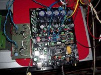
I had a look at MCgyvers picture and it looks like he has 3 bigger cap cans separate to the tube PCB.
If this is the case would this be a better board...see below, or will this just be overkill for my needs as not all circuits will fit anyway ?.
cheers
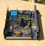
The Tamuras are on a specific board, because those I bought were with very short wire, I had to install with much more precaution , and would not have to move twice.
Resistors and caps around Tamuras are installed to be removed anytime I want, until tests ended (successfully ?)
I use Tamura with Buffalo ESS9008 Dac (Twisted Pear Audio), and have a McIntosh Pre C24, not sure to need a cathode follower.(althought I agree with McGyver about tamura 's output impedance)
Before Tamuras, I made a Broskie Cathode follower, with differential input, using 6GM8 and 24v "B+": sounds very nice but need 2 more transfos !
I'm a "Keep It Simple" adept
R.C.
shuggi67 said:
(...)
I had a look at MCgyvers picture and it looks like he has 3 bigger cap cans separate to the tube PCB.
If this is the case would this be a better board...see below, or will this just be overkill for my needs as not all circuits will fit anyway ?.
cheers
3 black cap cans are power supply for the tube (see the picture).
If you are going to use output transformers alone and omit tube buffer, you will not need this caps. Nor output caps (big blue boxes) either.
Attachments
- Home
- Source & Line
- Digital Line Level
- Experience with this DIY DAC ?