OK, I tried a couple of things:
First-off I reverted to the LPF on the board - it's series R 1K8 but I'm not sure what value the cap across the legs is - it looks like it's following the datasheet so it's 220pF for a cut-off of 402KHz?
Secondly with a 0.1uF PP cap in series on one leg & a connection to ground the sound is loud & clear.
When I connect a transformer primary across the 2 legs I get no sound out of the secondary just hum.
If I put a multimeter across a gnd & 1 leg on the pcb, I see a nice healthy fluctuating AC V when music is playing. When I put the mutimeter across both legs I see no fluctuating AC. I thought I should see about twice the level across I see 1 leg & ground?
The 1793 has a voltage out of 3.2 Vp-p and this is followed by a LPF & balanced gain stage based on OP275 op-amp, giving 77KHz cut-off & 1.83 gain to bring the voltage up to 5.9 Vp-p or 2.1 Vrms.
I'm not sure what you mean by no return to ground?
I guess I could bring down the LPF to about 70KHz as in the datasheet!
So if I put a R across the secondary legs, this is reflected back to the primary and seen by the DAC's output? What is the formula for that, if my trafo is 1:7.
The formula is the square of the ratio, for instance, if you put a 49Kohm R across the secondary the chip would see 1Kohm. That trafo indeed has a high impedance secondary. If you load down the secondary all the voltage will show up across your series resistors on the primary side with very little left across the trafo primary because it looks like a dead short compared to the series Rs.
With a 3.2v p-p that is over 1v RMS, should be usable with a 1/1 trafo but you could use 1/2 for more signal.
Grounds are signal returns in single ended equipment, and reference points in quasi-differential circuits. True differential circuits such as trafos do not require ground references, but some opamps do, and possibly some dac chips might also. I can't speak for your particular chip, but the CS4398 does not, and I would guess that yours does not.
I hope I was helpful.
OK, I tried a couple of things:
First-off I reverted to the LPF on the board - it's series R 1K8 but I'm not sure what value the cap across the legs is - it looks like it's following the datasheet so it's 220pF for a cut-off of 402KHz?
Secondly with a 0.1uF PP cap in series on one leg & a connection to ground the sound is loud & clear.
When I connect a transformer primary across the 2 legs I get no sound out of the secondary just hum.
If I put a multimeter across a gnd & 1 leg on the pcb, I see a nice healthy fluctuating AC V when music is playing. When I put the mutimeter across both legs I see no fluctuating AC. I thought I should see about twice the level across I see 1 leg & ground?
I guess I was writing while you were posting.
To use the trafos correctly you must completely isolate the chip's outputs, then check for a signal with your meter or scope.
The hum is probably coming from the opamp that internally has been compromised by placing the winding across the inputs.
I guess I was writing while you were posting.
To use the trafos correctly you must completely isolate the chip's outputs, then check for a signal with your meter or scope.
The hum is probably coming from the opamp that internally has been compromised by placing the winding across the inputs.
The other channel I did first & I isolated the tracks completely from the op-amp and took the diff signals through a 3K series R on each leg but I had a cap across the legs after the Rs. This gave no signal but hum! Should I use 2 caps to ground from each leg instead?
The other channel I did first & I isolated the tracks completely from the op-amp and took the diff signals through a 3K series R on each leg but I had a cap across the legs after the Rs. This gave no signal but hum! Should I use 2 caps to ground from each leg instead?
I did look up your dac chip and see no reason the basic trafo arrangement would not work brilliantly. The suggested filter/gain stage, if not totally disconnected, could cause numerous problems so you must be sure there is absolutely nothing else connected to the dac outputs but one end of a resistor, and the other end of the Rs should be run to the trafo primaries, and nothing else. The filter caps can be placed straight across the primaries.
If you're not getting a signal across the outputs of the dac chip then they must not be totally isolated. If yours is a multi-layer circuit board you could have many connections that you cannot see, you will have to pull the output end of the series Rs from the board, or pull them altogether and solder them to the trafos and run wires to the correct traces.
Honestly, this arrangement is very simple and straightforward and should be problem free. I've used 5 different trafos so far with zero problems.
.......... I've used 5 different trafos so far with zero problems.
Bill,
And have you got a favourite transformer with the DIY DAC with which most of us started? It would be very interesting to read your comparisons if you feel like giving a brief rundown of your subjective findings.
MAny thanks and good luck
Last edited:
I'm sorry to hog this thread but this is now bugging me.
I have differential signals now (it needed caps to gnd from each leg) and the sound is good but still a buzz/hum which ruins it.
I've tried 2 different trafos - one is a 1:1 Dave Slagle wound trafo for a preamp I'm putting together and the other is an encapsulated 16VA Talema mains trafo 115-0-115:22-0-22 so a 7:1. Both trafos have their primary & secondaries bridged. The 1:1 has a lot of buzz/hum, the 1:7 not as bad. Interestingly the 1:7 Talema sounds pretty good possibly because I imagine it's bandwith limited?
There is a 1.4V DC bias on the diff signals out from the DAC - could this have anything to do with it - I thought the trafo would be able to deal with this as it's differential & they seem balanced? I just tried some caps in series to block DC & still the hum?
It couldn't be this as I get hum even with just the trafo connected but it's worse when I connect the DAC which is a USB DAC, if that makes any difference
Last edited:
Bill,
And have you got a favourite transformer with the DIY DAC with which most of us started? It would be very interesting to read your comparisons if you feel like giving a brief rundown of your subjective findings.
MAny thanks and good luck
Hi Brian,
All the trafos I own I bought off of Ebay because I'm on a limited budget and also a cheapskate.😀
My best are the Sescom MI-14s they have the biggest soundstage width and depth, are very uncolored and are just a touch thin on bass, but just a touch. The mids and highs are very liquid in my system (Seas Excell/Pass Labs).
The UTC A-20s, which I borrowed are the bass monsters, staggering bass response for systems that can handle the full bottom octave of music. The mids are also outstanding, great vocal reproduction, soundstage and highs not nearly as good as the Sescoms, older core technology I assume. Overall slightly thick, but very enjoyable, would have kept them if they were mine to keep, I can switch between two trafos with my setup.
The UTC A-22s I had were noticably thin in the bass due to the air gap in the cores, but other than that they were uncolored and transparent with a big, wide soundstage, and better top end than the A-20s.
I have a pair of inexpensive Jensen JT-123s that I just could not get to sound right at all, very thin and lifeless. I will probably revisit these at some point to figure out what is going on with them.
My last pair are Sescom mic splitter trafos out of MS-11s. They shouldn't be able to handle the signal but I paralleled the primaries with a 270 ohm R and they are quite remarkable sounding, just lower output than the MI-14s.
The fun is in the experimenting, some day I might spring for some Cinemags or Lundahls, but I'm pretty happy with the MI-14s.
I connected a ground from the DAC board to the designated ground wire on the trafo secondary & it works on both trafos - dead silent (I don't have an explanation) - I can hear the quality of the trafos now - the Slagle is far superior (top to bottom ) to the Talema Mains trafo, as you'd expect. Unfortunately I have this allocated for a preamp!
Bill what sort of ballpark price are the Sescom M-14s as like you I'm a cheapskate & hope they're cheaper than the UTC A-20s?
Bill what sort of ballpark price are the Sescom M-14s as like you I'm a cheapskate & hope they're cheaper than the UTC A-20s?
I connected a ground from the DAC board to the designated ground wire on the trafo secondary & it works on both trafos - dead silent (I don't have an explanation) - I can hear the quality of the trafos now - the Slagle is far superior (top to bottom ) to the Talema Mains trafo, as you'd expect. Unfortunately I have this allocated for a preamp!
Bill what sort of ballpark price are the Sescom M-14s as like you I'm a cheapskate & hope they're cheaper than the UTC A-20s?
If it works, it works, that's great. I haven't a clue what exactly you have so I'm sure not going to second guess your success, just enjoy.
I paid around $50 shipped for the pair of MI-14s. Last I looked there was a pair of M-97s on Ebay that I would not be afraid to buy and try. Most all of the bigger (+18db and +30db) Sescom trafos were well over $100 when they were still making them.
I'd like to take the +/- supplies to the opamps and run them through a JLH power supply ripple rejection board that I have ready to use, but need a spot to take those supplies from, any suggestions?
The PCB is the V8 upsampling one as currently shipping.
The PCB is the V8 upsampling one as currently shipping.
I bought this DAC two months ago.
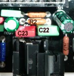
I would like to check the values of C22, C23 and R3 and if needed change them to the updated values given by Cirrus.
However, I do not have a schematic (Mr. Chan says he has none😡), and I really don't know where they are located on the pcb.
Could someone point them out on the enclosed picture (I guess they should be close to the CS8416)?
I would be really grateful!
Regards,
Lucas
Missed your post, I have an earlier version. Look right behind the dig. coax input jack. If you need to change them it is much easier to remove that jack first, but be very careful not to damage any traces, they are very delicate. I used a solder sucker to remove everything. Multi layer boards are a PITA.
Best, Bill
Hey guys, I don't want to hijack this thread with more of my questions so I'll start a new thread because I think this usage of transformers as DAC output stage should get a topic on it's own!
Missed your post, I have an earlier version. Look right behind the dig. coax input jack. If you need to change them it is much easier to remove that jack first, but be very careful not to damage any traces, they are very delicate. I used a solder sucker to remove everything. Multi layer boards are a PITA.
Best, Bill
Hi Bill,
Thanks for taking the trouble to help me out!
If I am not mistaking, the little red cap left must be C23 and the green one C22 (both straight behind the coax in). The first resistor might be R2 then?
The resistor is 1k Ohm and on the green cap there's written 0,22 (that means 220nF?), so I guess my DAC still has the old values in it...
Am I right? (I enclose a labeled picture of this part of the PCB with the names on it...)
Regards,
Lucas
Attachments
few questions
I have the new release of the DAC that does not come with the Sumlink chip, and I'm wandering where it goes on the board.
There is a space that could be it between the stereo out and digital in, from the picture.
But I'm not sure, does anyone know if its as easy as that i.e just plug the sumlink in??
thanks
Attachments


are the caps required
From the diagram it read that 2x 0.00047 caps are required, is this still the case ??

From the diagram it read that 2x 0.00047 caps are required, is this still the case ??
Problems?
Hello all,
I'm wondering if anyone else out there is experiencing problems with this board?
I have the v8 board (red) with edcor transformers for the output stage. I'm using the standard jensen design for filtering and loading the transformers. Power is from the included chinese toroid connected to mains through a line filter. Only the digital section is powered.
I'm listening with a PPAv2 headphone amp and grado 325i headphones.
For a source I've tried both the built in usb and a usb to coax spdif board based on the PCM2704 chip. I have also tried a usb to opt spdif board based on the PCM2002 chip. I'm running foobar with asio4all output and a variety of lossless and lossy files.
I've encountered several problems with this board, I'm wondering if anyone else has had similar problems, or if anyone has any ideas for a fix.
The first problem is with ocasional hiss in the left channel that disappears once playback is restarted.
The second problem is with pops/hesitations during playback.
When I first got the board I tried it out with the opamp output. When using the opamp section the output relay would click on and off. I'm a bit concerned that I might be getting dc garbage coming out of the chip. I just can't think of a good way of testing it.
My last problem probably isn't due to the board. I've tried hooking it up to a SSMH headphone amp and I've gotten terrible results. The sound quality is awful, flat, compressed, and dull. My SSMH has a little under 150k input impedance. I'm thinking that the dac chip just can't drive the high impedance of the amp and the solution would be some sort of output buffer. Any opinions?
The last thing I have to add is that after trying the board with upsampling and without I have to say that without sounds much much better. Maybe it's my setup or my board (my upsample board came with cheap electrolytics) but the sound quality went up noticeably after removing the upsampler. The upsampler also seems to have been making things worse as there are fewer pops and less hiss with it out of the system.
I'd appreciate any advice anyone can offer.
I have the new release of the DAC that does not come with the Sumlink chip, and I'm wandering where it goes on the board.
There is a space that could be it between the stereo out and digital in, from the picture.
But I'm not sure, does anyone know if its as easy as that i.e just plug the sumlink in??
thanks
I worked on one of those boards but I didn't trace out the input path. There is a link on the board somewhere that connects the input jack to the circuitry for the 8416. You'll have to find it and break that connection or the signal will bypass the sumlink rendering it useless. Sure would help if we had a schematic, wouldn't it.
Hello all,
I'm wondering if anyone else out there is experiencing problems with this board?
I have the v8 board (red) with edcor transformers for the output stage. I'm using the standard jensen design for filtering and loading the transformers. Power is from the included chinese toroid connected to mains through a line filter. Only the digital section is powered.
I'm listening with a PPAv2 headphone amp and grado 325i headphones.
For a source I've tried both the built in usb and a usb to coax spdif board based on the PCM2704 chip. I have also tried a usb to opt spdif board based on the PCM2002 chip. I'm running foobar with asio4all output and a variety of lossless and lossy files.
I've encountered several problems with this board, I'm wondering if anyone else has had similar problems, or if anyone has any ideas for a fix.
The first problem is with ocasional hiss in the left channel that disappears once playback is restarted.
The second problem is with pops/hesitations during playback.
When I first got the board I tried it out with the opamp output. When using the opamp section the output relay would click on and off. I'm a bit concerned that I might be getting dc garbage coming out of the chip. I just can't think of a good way of testing it.
My last problem probably isn't due to the board. I've tried hooking it up to a SSMH headphone amp and I've gotten terrible results. The sound quality is awful, flat, compressed, and dull. My SSMH has a little under 150k input impedance. I'm thinking that the dac chip just can't drive the high impedance of the amp and the solution would be some sort of output buffer. Any opinions?
The last thing I have to add is that after trying the board with upsampling and without I have to say that without sounds much much better. Maybe it's my setup or my board (my upsample board came with cheap electrolytics) but the sound quality went up noticeably after removing the upsampler. The upsampler also seems to have been making things worse as there are fewer pops and less hiss with it out of the system.
I'd appreciate any advice anyone can offer.
From what you have posted I would assume that your board was defective from the start.
The higher the input impedance of your amp the easier it is to drive, not harder.
It is a multi layer PCB, the solder connections must be solid all the way through the component mounting holes, double check all your mods for bad connections. You might have to solder both sides of the board.
Hi Bill,
Thanks for taking the trouble to help me out!
If I am not mistaking, the little red cap left must be C23 and the green one C22 (both straight behind the coax in). The first resistor might be R2 then?
The resistor is 1k Ohm and on the green cap there's written 0,22 (that means 220nF?), so I guess my DAC still has the old values in it...
Am I right? (I enclose a labeled picture of this part of the PCB with the names on it...)
Regards,
Lucas
That looks right but it's been so long since I changed mine I dont remember the correct values. You should be able to sort it out with the 8416 data sheet and the app note from Crystal. If someone has them handy please speak up.
- Home
- Source & Line
- Digital Line Level
- Experience with this DIY DAC ?