anyone tried the DIR9001 with this dac?
As you can see: Yes, I own a DIR9001 version.
But I cannot directly compare, as my other Gigawork DAC is different in another points (Lundahl, sample rate conversion).
Franz
John
Just thinking:
next step, cut the adequate pins from the daughterboard, connecting the audio outs to the motherboard.
Franz
Just thinking:
next step, cut the adequate pins from the daughterboard, connecting the audio outs to the motherboard.
Franz
In my setup the sound quality is improved across the board, not just the bass. It sounds awesome. I would love to know why difference in sound quality.
I have mine soldered to the pins under the chip with twisted pairs going output trafos. Should it make any difference whether they're on the top or on the bottom ?
I now have them soldered on top of the DAC chip,and I even soldered the leads from the pulstrafo on top of the CS8416 just incase it should make a difference...🙂 Havent had time to listen much yet..
John
Just thinking:
next step, cut the adequate pins from the daughterboard, connecting the audio outs to the motherboard.
Franz
Hi Franz!
Spookily enough I was thinking exactly the same thing last night when I couldn't sleep and the 'hifi' mind was active haha! I cannot imagine it would make much difference.... then again all that extra track might be acting like an aerial for RF so best to get rid of it just incase.
I'd love to know why the bass in particular improved so much just from this simple 'mod' - Bass sounds like REALLY good analogue now. Quite scarey on some tracks! Low level detail is astonishing too particularly on acoustic tracks or some classical. Amazing how much music IS actually there in 16-bit files. I have a Garrard 301 turntable but have to say this DAC sounds better in some respects - I'm not missing vinyl too much! Looking forward to trying out some 24-bit files tomorrow. I think CD was actually GREAT all along, it just took us a couple decades for the DACs to catch up 😉
- John
P.S. Another quick trick is to run a Densen (or similar) de-magnetising track through the DAC and output transformers. Those old UTCs really benefit 😉
Last edited:
Hello John,
were there resistors between the DAC chip and the L/R outputs that you've bypassed?
Cheers,
Dan
Not on my board, no. I just soldered directly to the first solderpoint coming out from the DAC chip (same solderpoint that the legs/pins are connected to).
However I have the Jensen output filter connected to the UTC A-20s (so I guess there actually are resistors after the dac!). Have attached it here. I just used R1/R2/R5/C1 and C4. The rest can be omitted.
Attachments
Last edited:
I have mine soldered to the pins under the chip with twisted pairs going output trafos. Should it make any difference whether they're on the top or on the bottom ?
I wouldn't have thought so, no.
I also preferred the sound without twisted wires - also results in slightly shorter wiring runs too if you untwist them. Then again my UTCs are directly next to the board. I'll get some pics up tomorow.
I now have them soldered on top of the DAC chip,and I even soldered the leads from the pulstrafo on top of the CS8416 just incase it should make a difference...🙂 Havent had time to listen much yet..
That's a good idea - I might try that! I was thinking of getting rid of the pulse transformer altogether - Many people seem to dislike pulse transformers on here thinking they do more harm than good.
This pulse trafo thing is driving me completely neurotic. As soon as I install it someone comes along and says it's not a good idea - so I remove it. As soon as I remove it someone comes along and says it's a must - so I put it back in. Must have done this a dozen times. Personally my ears can't tell anymore and I don't have the necessary equipment to test it.
I think I'm about to remove it again.
Do those of you who are NOT using pulse trafos but are soldering input directly to 4816 still place a 75R across +/-?
I think I'm about to remove it again.
Do those of you who are NOT using pulse trafos but are soldering input directly to 4816 still place a 75R across +/-?
It's something I've been meaning to do for at least 6 months now haha! I guess those extra solder points and traces degrade that signal by a surprising amount, in hindsight.
have a Behringer SRC2496 awaiting the output transformer mods, but I'd be very surprised if it bests the Gigaworks.
I believe the AKM chip in the Behringer is at least as good as the 4398 of the Gigaworks board plus the Behringer will let you easily control the upsampling functions from the front panel. I am waiting for the Behringer myself. I believe it will better the Gigaworks board.
We'll see....
This pulse trafo thing is driving me completely neurotic. As soon as I install it someone comes along and says it's not a good idea - so I remove it. As soon as I remove it someone comes along and says it's a must - so I put it back in. Must have done this a dozen times. Personally my ears can't tell anymore and I don't have the necessary equipment to test it.
I think I'm about to remove it again.
Do those of you who are NOT using pulse trafos but are soldering input directly to 4816 still place a 75R across +/-?
If you cannot hear a difference then I'd TRUST your own evidence, and ignore what everyone says about them. As with many things Hi-Fi quite often you'll always get polarising opinions. Best thing to do if you do want some kind of reassurance over what to do is try and find circuit digrams of a few commercial DACs and see what they've done. I think the pulse transformers are there to 1) rid coaxial connections of any possible DC and 2) to prevent any earth loops occuring. If you're clear of both of those then you don't need the pulse as far as I can tell.
- John
I believe the AKM chip in the Behringer is at least as good as the 4398 of the Gigaworks board plus the Behringer will let you easily control the upsampling functions from the front panel. I am waiting for the Behringer myself. I believe it will better the Gigaworks board.
We'll see....
Still plucking up courage to do the mods to the Behringer - the solder pads are SMT and apparently the AKM chips are VERY easy to damage with heat. May just leave it and sell it on stock. Very happy with the Gigaworks so perhaps should quit whilst ahead.
This pulse trafo thing is driving me completely neurotic. As soon as I install it someone comes along and says it's not a good idea - so I remove it. As soon as I remove it someone comes along and says it's a must - so I put it back in. Must have done this a dozen times. Personally my ears can't tell anymore and I don't have the necessary equipment to test it.
I think I'm about to remove it again.
Do those of you who are NOT using pulse trafos but are soldering input directly to 4816 still place a 75R across +/-?
 😀
😀I don't use one on the dac, all my sources have them.
Yes you still need the 75R across the jack to properly terminate the coax, and the cap between the chip and jack for dc protection. IOW, if you don't use a trafo use the original board wiring, it's right.
If you can t tell the difference with either your ears or whatever test equipment you have then dont bother. I generally go with that rule for everything. Trust my ears after all thats what will be used to listen to it. No point in having 'extra' parts in there unless they need to be there for a good reason.
If you can t tell the difference with either your ears or whatever test equipment you have then dont bother. I generally go with that rule for everything. Trust my ears after all thats what will be used to listen to it. No point in having 'extra' parts in there unless they need to be there for a good reason.
If I could A/B them I probably would notice a(slight) difference but between the time I listen to one setup, then unplug, de-solder/solder, plug-in, warm up and listen to the other setup my brain has forgotten what it heard the first time. Measurements would solve that dilemma.
If I could A/B them I probably would notice a(slight) difference but between the time I listen to one setup, then unplug, de-solder/solder, plug-in, warm up and listen to the other setup my brain has forgotten what it heard the first time. Measurements would solve that dilemma.
Have a look at pages 49/50 of the CS8416 data sheet - might give you some further ideas. I intend to implement Fig.18 directly to the solder points on the motherboard of the receiver bypassing the input transformer and anything else Gigaworks implemented here.
- John
Edit: datasheet available here (too large to upload): www.audiologic.com/en/pubs/proDatasheet/CS8416_F3.pdf
Last edited:
...I intend to implement Fig.18 directly to the solder points on the motherboard of the receiver bypassing the input transformer and anything else Gigaworks implemented here...
If I understand correctly...
RCA "+" goes to RXPO with a 0.01uF in line. RCA "-" goes to ground as does RXN with another 0.01uF in line.
Where would you ground RCA "-" and RXN?
Ok,I have been asked to upload a picture of where to cut the trace and where to solder the leads from the extra regulator (Salas or other).
If you look at the datasheet of LM317 http://www.national.com/ds/LM/LM117.pdf you see that the middle pin is the output,and that is the trace that is to be cut and the other regulator connected at the other end of the trace.
Here´s a picture of it:
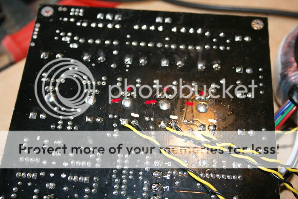
The red dots are the middle pin of LM317,the 3 red lines is where you cut,(If you arent going to use extra regulator on the USB,don´t cut the last one at the end of pcb)(follow the trace from(the middle)the red dot so you´ll cut the right trace.
The small silver line just above the black cable is to mark the negative on the e-lyt that´s on the otherside of pcb,you can check this so it´s right.
If there´s any questions feel free to ask.
Åke
If you look at the datasheet of LM317 http://www.national.com/ds/LM/LM117.pdf you see that the middle pin is the output,and that is the trace that is to be cut and the other regulator connected at the other end of the trace.
Here´s a picture of it:
The red dots are the middle pin of LM317,the 3 red lines is where you cut,(If you arent going to use extra regulator on the USB,don´t cut the last one at the end of pcb)(follow the trace from(the middle)the red dot so you´ll cut the right trace.
The small silver line just above the black cable is to mark the negative on the e-lyt that´s on the otherside of pcb,you can check this so it´s right.
If there´s any questions feel free to ask.
Åke
- Home
- Source & Line
- Digital Line Level
- Experience with this DIY DAC ?