I'll start with this question.(If you arent going to use extra regulator on the USB,don´t cut the last one at the end of pcb)(follow the trace from(the middle)the red dot so you´ll cut the right trace.
If there´s any questions feel free to ask.
Does this mean if you don't want a regulator on the USB you only need two and are you referring to the connection on the right side of the board?
Is it one for optical, one for coax and one for USB?
If that's the case can I get away with only one regulator on the coax circuit since that's the only connection I use?
Thanks
The USB regulator is the one in the blue ring on this photo:
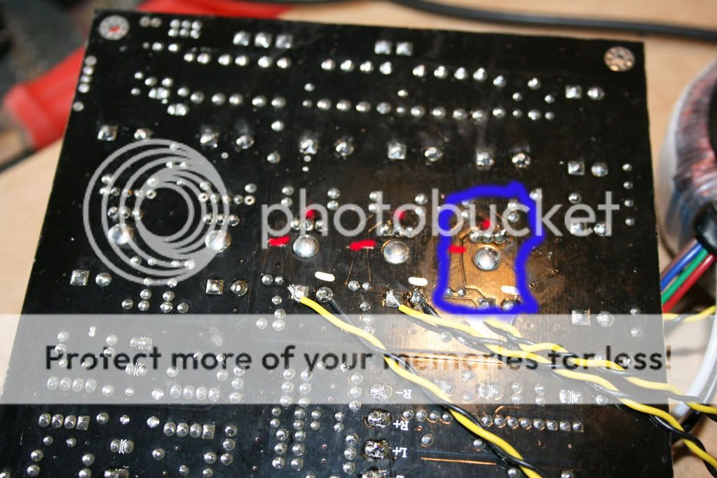
I followed the track from that regulator to the USB unit,I assume the optical is getting the power from one of the other two regs,the coaxinput doesn´t need any power.
The two 5v regs beside the USB reg is for the DAC chip and the CS8416 and the upsamplingboard.
The first 5v reg has a trace down to the optical input and to CS8416 (I belive)
And the middle 5V reg a trace to the DAC CS4398.
I forgott to add,that you still need to have 9v in on the PCB,because there are som small 3,3v regs that need power.I use the one trafo for this and for the Salas regs.
OK I understand.
Next question - You bought naked PCBs or fully assembled regs(link)? The fully assembled Teddy regs are $59 but if I calculate the PCB + all the parts that I would need to order + shipping I'm not sure if it's worth the hassle.
Next question - You bought naked PCBs or fully assembled regs(link)? The fully assembled Teddy regs are $59 but if I calculate the PCB + all the parts that I would need to order + shipping I'm not sure if it's worth the hassle.
I bought the salas PCB http://www.diyaudio.com/forums/digital-line-level/137976-experience-diy-dac-210.html#post2080502 from Mr quanghao
they are 15$ each (2, +5v regs on each pcb)and the components for 3,+5v regs,(I bought the components in Sweden)is about 100$.
I´m thinking if you buy a comersial DAC like Benchmark DAC1 they dont have discrete regulators,and I think this one sounds better.
And then it´s fun to build and experiment.
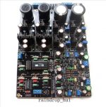
I have put the finishing touches on my Gigawork: Switched from 500R and 1nf on primaries to 220R and 7nf per Legarem's recommendation. replaced Takman resistors w/ Shinkoh and Wima X-type(?) caps w/ RELcap polystyrenes.
Surprisingly the bass increased a couple notches (I thought the 500R rec was for bass), didn't expect that. Sound is rich and creamy. Sounds a lot cleaner. What a difference compoenents make. Or maybe it's the filter. Anyhoos, I hereby declare this project finished!
however, I did order this guy because of Lampizator's (Lukasz) view that it's better than the cs4397/8 DACs, and requires much less fuss.
Attachments
Last edited:
Looks promising.
Those Chinese are pulling new DACs out of their ***** every 5 min. I'll milk the Cirrus DAC for a few more tweaks but than I'll be taking it easy during the summer. Hmm I said that last summer.
Those Chinese are pulling new DACs out of their ***** every 5 min. I'll milk the Cirrus DAC for a few more tweaks but than I'll be taking it easy during the summer. Hmm I said that last summer.
If the SuperTeddyRegs or other regulators that DON´T have a rectifier on the pcb (The Salas have it on pcb) is to be used.
You take the power to the input on the regs on the green dots on this photo.
(You might wanna messaure that there is about 12-14v(depending on the trafo used)at these points,there should be..)
The soldering point next to the green dots are the ground.
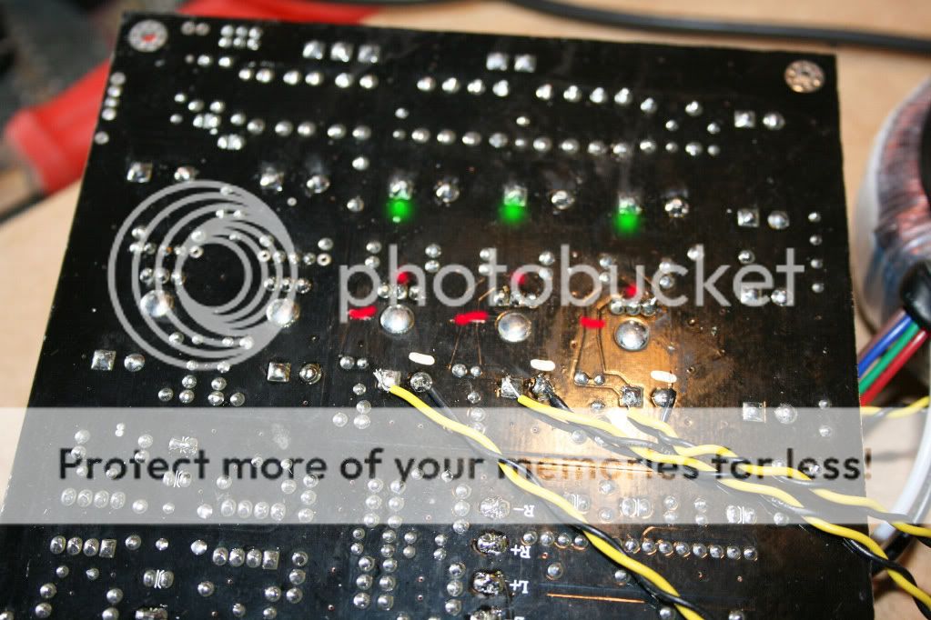
And the output from the regs connected where the yellow cables are.
You can ofcourse use an external rectifier and e-lyt,but I´d prefeer to take it by the green dots.
You take the power to the input on the regs on the green dots on this photo.
(You might wanna messaure that there is about 12-14v(depending on the trafo used)at these points,there should be..)
The soldering point next to the green dots are the ground.
And the output from the regs connected where the yellow cables are.
You can ofcourse use an external rectifier and e-lyt,but I´d prefeer to take it by the green dots.
Last edited:
@Ryssen - Everything remains intact on top of board(caps, etc) and you still need to cut traces as shown - correct?
Yes,that is correct.
You could remove the original regulators (LM317) if you like but,I left it on the board.If you REMOVE them you don´t have to cut the traces,that is only if you remove them...
Edit:If anyone have a software that can make a simple schema, e-lyt--regulator--e-lyt.
It would be easier to se..
You could remove the original regulators (LM317) if you like but,I left it on the board.If you REMOVE them you don´t have to cut the traces,that is only if you remove them...
Edit:If anyone have a software that can make a simple schema, e-lyt--regulator--e-lyt.
It would be easier to se..
Last edited:
Yes,that is correct.
You could remove the original regulators (LM317) if you like but,I left it on the board.If you REMOVE them you don´t have to cut the traces,that is only if you remove them...
Edit:If anyone have a software that can make a simple schema, e-lyt--regulator--e-lyt.
It would be easier to se..
Ryssen
1. There's 2 resistor for each LM317, do we have to remove it or replace with a jumper?
2. Is it possible to use on board rectifier to rectify the voltage then use the power point at green point for TeddyReg input and output it to where you solder the Yellow-Black wire...???
Thanks for the picture....
If you cut the trace and leave the LM317 on the board,leave the resistor to,(I have not removed them).1. There's 2 resistor for each LM317, do we have to remove it or replace with a jumper?
If you remove the LM317,remove the resistors to.
Exactly.2. Is it possible to use on board rectifier to rectify the voltage then use the power point at green point for TeddyReg input and output it to where you solder the Yellow-Black wire...???
And either cut the trace and leave Lm317+resistors on board----Or remove LM317+resistors and NO cut.
Edit:Another option if you decide to remove the LM317 and NO cut,is to solder the wires through the holes of the removed LM317(on top of the board)then you have to look at the datashet for LM317 and se what holes are in and output,just a thought....
Last edited:
If you cut the trace and leave the LM317 on the board,leave the resistor to,(I have not removed them).
If you remove the LM317,remove the resistors to.
Exactly.
And either cut the trace and leave Lm317+resistors on board----Or remove LM317+resistors and NO cut.
Edit:Another option if you decide to remove the LM317 and NO cut,is to solder the wires through the holes of the removed LM317(on top of the board)then you have to look at the datashet for LM317 and se what holes are in and output,just a thought....
I prefer the last option...remove the regulator and use the input & output holes for the new regulator...but I think those 2 resistors need to be remove since it's in the output line....
 By ImageHousing.com
Last edited:
Yes,if you remove LM317 remove resistors. 🙂
If my regulator use a different transformer and have it's own rectifier can I remove the big lytic resevoir caps on the dac board?
Yes,you can remove them,they are of no use then.Just remember to use an e-lyt about the same size after the new rectifier (unless there is an e-lyt at input of the new regulator,that is).
Yes,you can remove them,they are of no use then.Just remember to use an e-lyt about the same size after the new rectifier (unless there is an e-lyt at input of the new regulator,that is).
But how about the tiny 3.3v regulator....there's 2 of the if not mistaken...?? Don't they need some reserve power from a e-lyt caps too....???
I´m thinking the smaller e-lyts at the side are for the 3,3v.
But to be shure use lamp and a Magnifying Glass and follow the traces from the rectifier,then you´ll se if the biggest e-lyts are involved in the 3,3voltage.
Report what you find out.. 🙂
But to be shure use lamp and a Magnifying Glass and follow the traces from the rectifier,then you´ll se if the biggest e-lyts are involved in the 3,3voltage.
Report what you find out.. 🙂
I´m thinking the smaller e-lyts at the side are for the 3,3v.
But to be shure use lamp and a Magnifying Glass and follow the traces from the rectifier,then you´ll se if the biggest e-lyts are involved in the 3,3voltage.
Report what you find out.. 🙂
will do bro...
I wouldn't have thought so, no.
I also preferred the sound without twisted wires - also results in slightly shorter wiring runs too if you untwist them. Then again my UTCs are directly next to the board. I'll get some pics up tomorow.
Pics..?😉
- Home
- Source & Line
- Digital Line Level
- Experience with this DIY DAC ?