It looks doable - but I would need more exact dimensions of the mounting plate.
The headphones go to my WTB list🙂
The headphones go to my WTB list🙂
Last edited:
I corrected the inner dimensions of the front attachment since the test print went out slightly smaller (from now on I will heed to "measure twice, 3D print once" rule 🙂 ) and I prepared a slice of the attachment for a new test print.
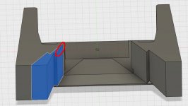
I also added a part that turns the 90° horizontal angle to 50° (shown in blue). I am actually considering making it a part of the whole print. Any tips on how to make the transition from 90° to 50° better? I could think only of making the part before the step for the 5 mm side a part of a circle instead of flat (marked in red). The edge is ca 21 mm long. It could be made longer if it was worth doing that. But it cannot be moved closer to the membrane (or only some 5 mm) because there the metal inserts start. Or can I go deeper down from the acoustic point of view? It would be a bit of challenge to get it correct but a thin foam strip could be used to seal against the metal plates - if that can be done without affecting the sound quality.
Edit: A picture is worth a thousand words. Now I have the transition starting at the red line. If there was some benefits, I think it could go easily to the blue line and even to the green line with a bit of challenge and using the AMT reversed (logo to the back).
Attachments

Last edited:
If it means anything Pelanj I was planning on having the logo side to the back as getting an adapter to fit on the on the front seems far easier without the logo being there - seeing as it won't be any more difficult to fashion a plug of sorts for the back with the logo there. Besides, in the horn, you won't be able to see the logo anyway.
If it were me I would aim for the blue line, but that is only due to gut feel and with no knowledge or experience of these drivers!
Are you now going for 50 degrees horizontal dispersion rather than 90? If so, the horn you are planning on making will be enormous!
If it were me I would aim for the blue line, but that is only due to gut feel and with no knowledge or experience of these drivers!
Are you now going for 50 degrees horizontal dispersion rather than 90? If so, the horn you are planning on making will be enormous!
Yes, I see the logo only as a mechanical obstacle🙂 With a few test prints, I should be able to go down to the green line. For 90 degrees, the red line is perfectly fine. For less, there may be some benefit going deeper.
I am open to both options at the moment, not yet decided. My size limit would be about the size of an SH-50, which is 28"x28" - its pattern starts to widen at 630 Hz and is 90 at 400 Hz (if I interpret the CF2 files correctly).
I am open to both options at the moment, not yet decided. My size limit would be about the size of an SH-50, which is 28"x28" - its pattern starts to widen at 630 Hz and is 90 at 400 Hz (if I interpret the CF2 files correctly).
I will be re-organizing my work room as a dedicated listening room - the only problem being it is pretty small - but it has two empty ca 90 x 90 cm corners. I expect that the AMTs in one of the projects will make it to this room as the ultimate sound solution. So I think I should think about this beforehand and design in a way that the project may be placed in a corner as well - including the bass bins. I cannot use the huge bass horns in these corners, but nc535's corner synergies with corner bass bins look like they would fit in nicely.
{title} (avec images) | Haut parleur
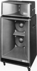
That is the Blue Ox that ESS produced in the late '70s
It would be great if there was more info related to the high frequency driver structure.
Notice the acoustic lens in the middle? Wonder what horizontal degree they were shooting for.
At any rate, since 3D printing is abundant these days, a guy could copy the structure for a horn loaded pleated diaphragm ... provided they had more info related to the design. I know that there are some examples of the rare Blue Ox in existence. Might ESS have one collecting dust in the warehouse?
Rock on!
The horn looks quite good. When I have the model of the front attachment ready, it can be used with any type of horn in front.
I never heard of the Blue Ox before but looks like a tractrix horn. I might have to try putting a foam core tractrix on my AMT-1. Very cool.

Attachments
Last edited:
https://adn.harmanpro.com/site_elem.../2301-2390-2391-2392-2395_manual_original.pdf
Are you guys overlooking the tweeter structure at the bottom of the link I posted?
Are you guys overlooking the tweeter structure at the bottom of the link I posted?
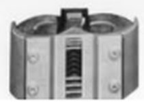
Might need my eyes checked but if you look at the amt in the left hand picture, you can make out a "scoop" of sorts behind the vertical bars just below the acoustic lens. If the top is like that then I'm thinking they just used the center 1/3rd of the diaphragm to produce the output at the lens section. So, the dark portion is all that sees the diaphragm. The silver sections below and above are ramped up/down to the center lens. This makes sense as the diaphragm center has the highest output. Their design would eliminate the "damped" upper/lower portions of the diaphragm.
A guy could make a plug that would nest inside the "v" of the Heil close to the diaphragm killing top/bottom output leaving a vertical center for starters. The outboard part of the plug could incorporate an attachment flange, much like the photo, to mate a horn to.
A guy could make a plug that would nest inside the "v" of the Heil close to the diaphragm killing top/bottom output leaving a vertical center for starters. The outboard part of the plug could incorporate an attachment flange, much like the photo, to mate a horn to.
Last edited:
This is my first try for a 90x40 horn attachment - meant for 5mm foamcore or plywood. Do not print this one! It is provided only for viewing. There would be way too much filament wasted. It needs to be cut down, instead of the thick walls, vertical ribs will be used.
Hi Pelanj,
Do you have the final STL or STEP model yet for the throat adapter suitable for printing?
Thanks,
X
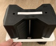
I printed a test slice yesterday and it seems to fit well. The 90x40 for 5 mm material is ready, I will share it here when the kids go to bed. I did not have time or filament to print it yet.
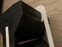
I did have a few free minutes waiting for the dinner🙂 Here is what I have - the 90x40 attachment half, 50 deg insert (for 50 degrees I will actually try to go closer to the diaphragm with the model). These are STEP files, so feel free to modify🙂 Also, there is a test slice that fits my AMT pretty well - I used it to test how it would fit the front.
Attachments
Last edited:
That's a beautiful fit. Sorry I don't follow what you mean by the adapter is 90x40 deg but the insert is 50deg? Shouldn't they be the same?
Please look at post #62 - the insert narrows the horizontal angle to 50 degrees from 90. You would need 2 + 2 mirrored or joined before printing with the 90 deg model.
I don't mean to hijack the thread here, but I do have a quick question. I have been warning to use the large Heil AMT with a professional 8" mid woofer, crossed as low as 1800 hz. Can anyone recommend a good 8" pro mid woofer for this application? Maybe you have already tried this? Thank you
That's a terrific model you've done Pelanj. I hope to be able to use it or build upon it when I design my next set of speakers, after moving to a bigger house, hopefully this year.
The Heil is designed to cross much lower than that. It actually works well at 800hz and is sort of like a FAST alignment. I am looking at using a pair of B&C 8MDN51-16ohms in parallel.
- Home
- Loudspeakers
- Multi-Way
- ESS AMT-1 in my projects