Now you see why Jack was looking at laying out a smaller board.
One of my sister's is a quilter, the other a painter...it has to look nice. Compact is ok as compact wants, but minimalism can set you down the wrong path.
My "His Master's Noise" board is pretty big for an MC stage and sits in the carcase of an Eico 378 Signal Generator:
Attachments
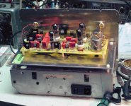
And that doesn't include the heater regs! 😀
Nor the power supply box full of transformers, diodes, caps, and such.
My "His Master's Noise" board is pretty big for an MC stage and sits in the carcase of an Eico 378 Signal Generator:
I like that look too. Thanks for the picture. "His Master's Noise" and the Equal Opportunity are similar enough that it gives me a better idea what the boards will look like when populated. I always think of Wima caps as pretty small, but some of these are half as tall as the tubes!
Beauty is in the eye (and ear) of the beholder (or is that the builder?).
RIAA Caps Volt Rating
I am curious about the RIAA caps and their voltage rating. Perhaps naively, I think the voltage that caps themselves see should be very low. With an input of 5 mV and a first stage gain of 33, the caps should see a couple hundred mV. Am I missing something?
I ask because I have some nice caps in my drawer, enough to do some matching, that are 100 V and 150 V rating. Also, the options in caps at the boards lead spacing improves when lower voltages are improved.
Yes, the EQ caps only see the difference in voltage between the two outputs (even though they float at the B+ DC level). C4 and C5 take all of the DC so should be 200V or better.
Confirming B- Raw Power Supply
Boy, things are sure quiet on this thread. I feel like I should be tip toeing in stocking feet.
I am looking at the B- raw power supply design (using PSUD2, of course). Looking at the circuit, the pFETs should draw almost nothing and R1/R2 draw microamps. The regulator looks like it draws about 13 mA through the voltage divider resistors. Is that 13 mA a good raw supply current or am I missing something?
Thanks in advance.
Jac
The pFETs draw the same as the tubes (since they're in series), i.e., 4mA per FET. So total draw for the 4 gain blocks is 32mA. That's pretty easy to do.
Confession: I used a power brick from a dead laptop (19V) for a raw supply. That gives me about a 100x over rating for current.
Confession: I used a power brick from a dead laptop (19V) for a raw supply. That gives me about a 100x over rating for current.
Confession: I used a power brick from a dead laptop (19V) for a raw supply. That gives me about a 100x over rating for current.
Popular amongst the class-D folks and available on Amazon for about $7. Shipped.
I obtained mine from dumpster diving. 😀
Interestingly, there's a lot of difference in noise output between supplies. A few show significant spikes which can be filtered out, but why bother when other bricks are dead quiet. The Lenovo brick was the best of all the ones I had on hand.
Interestingly, there's a lot of difference in noise output between supplies. A few show significant spikes which can be filtered out, but why bother when other bricks are dead quiet. The Lenovo brick was the best of all the ones I had on hand.
Way off Topic
Sy,
Have you found any good electronic surplus stores in Chicagoland? If you could recommend one, I will be spending some time around the holiday visiting family in that area and would love to dive into a few parts bins.
Alas, the last of the good electronic surplus stores in Michigan closed in the 2008 mess.
Jac
i'm not SY, but ....
sadly, no, not any more.
there were several when I moved to the area over 30 years ago, but i think they've all closed up.
man, i sound so old saying crap like that.
but i still remember poly paks and delta electronics for surplus.
🙂
mlloyd1
sadly, no, not any more.
there were several when I moved to the area over 30 years ago, but i think they've all closed up.
man, i sound so old saying crap like that.
but i still remember poly paks and delta electronics for surplus.
🙂
mlloyd1
Never even got a hint of one here. Last electronics surplus store I ever visited was back in my California days, the Aladdin's Cave that we called Halted.
It's pretty much an extinct species.
It's pretty much an extinct species.
The one in Ann Arbor was called "AJ's Radio" or something like that. I'm guessing it had been there since before the transistor was invented. A dark and wonderful place.
Oh well. Memories of better days. Thanks to both ML and SY.
I guess ebay is the new surplus store. Scary.
Jac
Oh well. Memories of better days. Thanks to both ML and SY.
I guess ebay is the new surplus store. Scary.
Jac
I'm getting close to bread boarding the CCS circuit and selecting R8 and R32 to get 4 mA. I know in theory, a CCS doesn't care what voltage is across it, but I'm curious to know how simple I can make this bread board circuit. For example, is it as simple as using a +15 VDC bench power supply at the Drain of Q6, an ammeter in line, and ground at the bottom of R8/R9?
Jac
Jac
Happy New Year, Y'all
I thought I would get a little time in matching parts before the partying starts.
Given a population of JFets, I know that they need to be closely matched for Idss and gm. Assuming I can find matches at different levels of Idss, what is ideal, given the 4 mA idle current? The first few parts I have checked show me a range of -3.9 to -6.3 for Idss.
Jac
Anything above 4mA will work- most of the ones I used were like 7-9mA (if memory serves). One trick: since the tube section match may not be great (the tubes I used were actually very tight, but most ECC88 variants aren't), if the plate voltages are mismatched by more than 10V or so, try swapping the FETs.
Thanks for the guidance. I finished my FET testing this morning and it looks like I will be able to match pairs in the 5.5 to 6.5 mA range.
That's a good tip on section balance! The tubes I am planning on using have section balance within 4% of each other. Hopefully, that is close enough. But it's nice to know that I could fine tune that if the plate voltages vary too much in practice.
Enjoy the holiday.
Jac
That's a good tip on section balance! The tubes I am planning on using have section balance within 4% of each other. Hopefully, that is close enough. But it's nice to know that I could fine tune that if the plate voltages vary too much in practice.
Enjoy the holiday.
Jac
Anything above 4mA will work- most of the ones I used were like 7-9mA (if memory serves). One trick: since the tube section match may not be great (the tubes I used were actually very tight, but most ECC88 variants aren't), if the plate voltages are mismatched by more than 10V or so, try swapping the FETs.
This is where machined 0.100" female molex headers come in handy. Just snip off a 3-some and you can swap to your heart's content.
This is where machined 0.100" female molex headers come in handy. Just snip off a 3-some and you can swap to your heart's content.
Yes, I improvised sockets by snipping a 6 pin DIP socket in half.
- Home
- Source & Line
- Analogue Source
- "Equal Opportunity" MM Pre