I've at least one set, maybe two. I too have to remember where I put them, and I won't be back to the house for a couple weeks.
To both billshurv and JP thank you and no worries. I will wait patiently for those PCB's to surface again some day.

Yeah we're busy with lots of things. Finished some tests for reviews SY is going to write as well. The SP-10 is still in a box somewhere I'm afraid.
On The Equal Opportunity: we have plans for those spare boards so we can't give them away right now.
But here's an alternative: I will update the board in two areas: one, we need to add a resistor in the input circuitry to improve CM rejection. Two, I should move the current source DN2540's a bit apart as they are quite close and the metal tabs could touch if not careful.
I can do that this week, and then I can post the Gerbers if anyone wants to get them made or organize a Group Buy.
Is that a plan?
Jan
SY SP-10
What do you get when you Google SY SP-10?
It might be a new look for SY.
What do you get when you Google SY SP-10?
It might be a new look for SY.
Attachments

Last edited:
Sounds like a good plan to me Jan,
Thank you for your generosity.
I hope SY is well; I've learnt a lot from his postings and articles.
t
Thank you for your generosity.
I hope SY is well; I've learnt a lot from his postings and articles.
t
It's been quiet here for about two weeks now. Jan, where do you plan on adding the resistor for improved common mode rejection?
It's been quiet here for about two weeks now. Jan, where do you plan on adding the resistor for improved common mode rejection?
Sorry, forgot all about it. I'll see if I can do it the next few days.
Jan
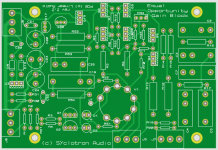
Here it is. The .CADCAM is the set of Gerbers for your PCB baker.
Note that the stuffing guide is shown with the ground plane removed for clarity. So it may look that a few connections are missing but they are all there through the ground plane.
Have fun!
Jan
Note that the stuffing guide is shown with the ground plane removed for clarity. So it may look that a few connections are missing but they are all there through the ground plane.
Have fun!
Jan
Attachments
Last edited:
I've looked at your cct and pcb files. I believe that I understand what you have changed on the PCB to include R21. I'm not sure that I understand the way it is drawn in the cct file. In the cct R1 and R2 seem to connect to ground only via R21. There might be a small circle still missing or else I just got lost somewhere.
Hi Guys;
Been a LONG time. I got super busy with work and some house projects and my lab got overrun with other stuff, so the EO preamp project sort of stalled.
Now that we are sheltering in place over COVID-19, I am starting it back up.
When last I posted, I had the raw supply up and running, the preamp boards were operational, and I was starting assemble the overall two channel preamp. What I found was that it worked fine as long Is was only using a single channel. The minute I hooked up the other channel, the tube filaments would fade off after about 15 seconds. I finally figured out that the single heater regulator could not support both channels without going into thermal shutdown.
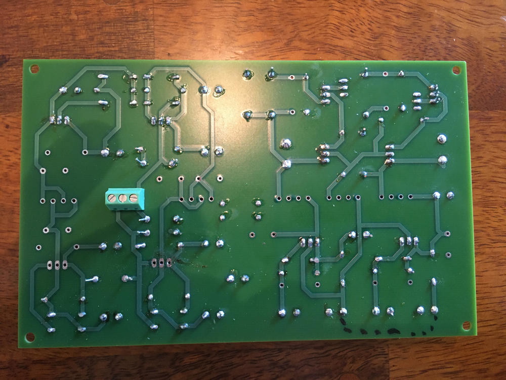
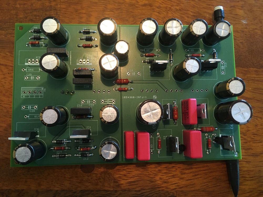
I ended up redoing the regulator board so it has a dual heater regulator. It's quite a lot larger, but should work fine. Here's a pic of that. I am waiting on a few random parts from Mouser to finish this off. And then I can't back into tuning up the overall amp.
One thing I did on this board was use separate ground planes for the supply ground (signal ground) and the heater "ground". You can see the two ground planes divided just to the left of the left-most red WIMA cap. The voltage divider that elevates the heater "ground" is formed by the two resistors that cross the gap (one os oversized..it was what I had lying around). I still need to put in the 317 regs (amazed that I don't have any of those!), some of the smaller caps, and the terminal blocks. This effectively provides a "ground plane" for the heater circuit, but that ground plane is actually elevated above signal ground.
Here is the new board. You can see my one booboo...didn't connect two overlapping wires on the schematic, so there will be a short jumper (dotted line)..I also forgot to do the silkscreen on the bottom to label the connections..It's always something... In my next iteration of this board, I also plan to allow a little more room between the regulators and the caps. .
As I was getting my head back into this project, I re-discovered the few odd differences between the various incarnations of the schematics. Specifically the 1 nF input cap on the 337 negative supply regulator. The 337 data sheet uses a 1 uF cap here, and on the output, for their "high stability" regulator example. I ended up using both a 0.1 uF and a 220 uF cap on both the input and the output. I am hopeful that this will kill both ripple and high frequency noise.
Not super sure if my ground plane approach is a good one or not. The use of a ground plane should eliminate the inductance of a bunch of traces all trying to converge to a single point, but it may also provide a plethora of potential "loops". Of course those loops are also all shorted together in a distributed fashion, so we'll see.
I'll keep y'all posted.
Scott
Been a LONG time. I got super busy with work and some house projects and my lab got overrun with other stuff, so the EO preamp project sort of stalled.
Now that we are sheltering in place over COVID-19, I am starting it back up.
When last I posted, I had the raw supply up and running, the preamp boards were operational, and I was starting assemble the overall two channel preamp. What I found was that it worked fine as long Is was only using a single channel. The minute I hooked up the other channel, the tube filaments would fade off after about 15 seconds. I finally figured out that the single heater regulator could not support both channels without going into thermal shutdown.
I ended up redoing the regulator board so it has a dual heater regulator. It's quite a lot larger, but should work fine. Here's a pic of that. I am waiting on a few random parts from Mouser to finish this off. And then I can't back into tuning up the overall amp.
One thing I did on this board was use separate ground planes for the supply ground (signal ground) and the heater "ground". You can see the two ground planes divided just to the left of the left-most red WIMA cap. The voltage divider that elevates the heater "ground" is formed by the two resistors that cross the gap (one os oversized..it was what I had lying around). I still need to put in the 317 regs (amazed that I don't have any of those!), some of the smaller caps, and the terminal blocks. This effectively provides a "ground plane" for the heater circuit, but that ground plane is actually elevated above signal ground.
Here is the new board. You can see my one booboo...didn't connect two overlapping wires on the schematic, so there will be a short jumper (dotted line)..I also forgot to do the silkscreen on the bottom to label the connections..It's always something... In my next iteration of this board, I also plan to allow a little more room between the regulators and the caps. .
As I was getting my head back into this project, I re-discovered the few odd differences between the various incarnations of the schematics. Specifically the 1 nF input cap on the 337 negative supply regulator. The 337 data sheet uses a 1 uF cap here, and on the output, for their "high stability" regulator example. I ended up using both a 0.1 uF and a 220 uF cap on both the input and the output. I am hopeful that this will kill both ripple and high frequency noise.
Not super sure if my ground plane approach is a good one or not. The use of a ground plane should eliminate the inductance of a bunch of traces all trying to converge to a single point, but it may also provide a plethora of potential "loops". Of course those loops are also all shorted together in a distributed fashion, so we'll see.
I'll keep y'all posted.
Scott
Last edited:
- Home
- Source & Line
- Analogue Source
- "Equal Opportunity" MM Pre