Is the group by moving ahead? Is there a BOM available or a basic cost estimate not including case? Thanks!
Thanks Jan. It looks like it wouldn't be hard to add R21 to an old board with a bit of point to point wiring. Can you give us an idea of the improvement in common mode noise with R21?
Jac
Jac
I’m curious to hear if anybody’s using an Equal Opportunity for making digital rips of their vinyl and what kind of gear they’re using for the ADC, especially if the gear comes in kit form.
I have actually been working on a digital system that supports multiple different source inputs: Analog (line level balanced), FLAC, AAC, MP3, PCM (CD), etc. at 44.1, 48, 96 and 192 kHz. Everything gets converted to 24 bit 192 kHz samples, and then run through a DSP to support active crossover and room equalization. It all gets run back out through a DAC to the amplifiers (tri-amped).
The ADC I am using is a Burr-Brown/TI PCM 4222 24 bit running at 192 kHz. The DAC is a TI PCM5122, 32 bit operating at 192 kHz. You need 32 bits on the DAC so that the digital volume control doesn't drive you down into the noise at lower volume levels (which is where most listening actually takes place.
I ahem this almost ready for breadboarding using eval boards and a couple of my own boards. The front panel controls are digital I/Q encoders. I use s PIC to interpret the encoders and then command the DAC and the rate converter (TI 4392 ASRC), and the streaming, codecs, and user interface (iPad/Phone) are implemented using a RaspberryPi.
So this system doesn't Rip. It could, but instead I plan to just play vinyl and rip to digital it on the fly every time it is played.
Thanks Jan. It looks like it wouldn't be hard to add R21 to an old board with a bit of point to point wiring. Can you give us an idea of the improvement in common mode noise with R21?
Jac
Looks like an interesting adjustment to the circuit. The original returned the balanced inputs to ground through R1 and R2. As SY and a few others pointed out relative to heater grounds, in a balanced configuration, the "ground" is sort of virtual. In the original configuration, R1 and R2 returned to actual ground. I suspect this tends to limit CMR, since each signal is referenced to ground, as opposed to the other signal. By removing them from a hard ground they are now referenced to one another. I suppose you could do without R21 entirely, but then with no DC return path, the balance would be super critical.
On my board, I think I can do this simply by lifting the grounded ends of R1 and R2 (shown below) and jumpering them together. I'll then use two 2 M resistors to connect the lifted and jumped ends back to ground...sort of an A-frame of resistors with a ridge pole jumper!.
I think I'll wait until the preamp is fully operational before I do this.

The blue one is from Edcor. It was a special order. It has 120/CT/120 and 12/CT/12 windings.
I am, however, slightly confused. I scaled the primary for this from the HMN power supply, and it works, but I am not sure why it works.. Based on my understanding of rectifier theory, the DC output of a full wave rectifier should be 0.637Vp, where Vp is the peak value of the half cycle. For 120 Vrms, the peak should be ~171 volts, and this should, theoretically produce a DC level of only 109 volts (=171*.637). However, the circuit produces about 169 volts. I am not sure if the theory is using an un filtered assumption and, with no load, the choke and capacitor are simply filling in the low spots, or I don't understand the theory I have been reading.
Managed to answer this for myself.
An UNFILTERED full wave rectified sine wave will have an average value of 0.637Vp, where Vp is the peak half wave AC voltage. The filter will supply the missing voltage between peaks, and thus the resulting DC will be approximately equal to the peak AC voltage, which is what we see in my raw supply. The key error I was making is assuming that the energy delivered by a DC supply is the equivalent of the RMS AC at the transformer output. This is true, but only when there is no filtering.
Once the signal is filtered, the resulting DC will be the RMS value of the ripple plus the value of the lowest part of the ripple (the DC component). If the ripple is symmetrical (e.g. a sinusoid), then it will add half the ripple value to the DC component as equivalent DC voltage. If it is asymmetrical, then the RMS value may add or subtract slightly from the DC component, depending on the asymmetry. For example the ripple from the filter cap can be approximated by a triangle wave with a fast rise time and a long tail. If this was, for sake of discussion, 1 volt peak to peak, then the RMS value would be 0.333 volts How to Derive the RMS Value of a Triangle Waveform – Mastering Electronics Design.
So, unless the cap is way undersized, the ripple will have very little impact and the DC voltage output will be very close to the PEAK AC voltage.
Good to know..
Last edited:
SY and others are proponents of Duncan's PSUD2, a power supply simulation program (free). Naturally, I was introduced to the program on this build and I found it to work very well. Its actually quite detailed in the way it treats transformers, filters, etc. I found it to be a good way to think through choices in a power supply and learn things I didn't know.
PSUD2
PSUD2
Yeah, I downloaded that. Unclear how to change the topology. Everything seems to be full wave bridge. The explanation of how to use it for a CT full wave (2 diode) was very unclear. I'll explore it in more depth.
It looks like my summary above is consistent with what it produces.
It looks like my summary above is consistent with what it produces.
Its a little tricky at first.
Topology is changed by right clicking on the "Bridge" area at the bottom of the sketch.
If you double click on the transformer, then the button next to the RMS V, you can fill in thing like open circuit voltage, etc and have it calculate effective impedance.
Also, the load section (near the bottom on the right) can be changed between resistance and constant current. Constant current is usually closer for tubes. The filter also can add sections for more complicated filters.
Of course, your rule of thumb calculations work for most projects. The program is helpful when you have more or less than typical voltage drop on the transformer, for example.
Anyway, I hope you find it useful.
I have tested most of the bits. Waiting in a new filament transformer (the current one is bit too hot for the +/- 3 volt filament circuit, so the regs get a little hot.
Ready to try out some LPs!!


Ready to try out some LPs!!
Last edited:
Nicely done! You are clearly a creative thinker with things upside down and standing up. The tubes will make a nice display in a dark room with the mirrors. Enjoy.
Hey Lehmanhill;
I have a question about your heater supply. I have been having a devil of a time getting mine to work properly.
I am using SY's HMN design modified for 6.3 volts (±3.15) with the common point floating about 30 V above ground.
Everything works great except I have about 0.5 volts of ripple on the heater lines. If I remove the tubes, I get perfect ripple free ±3.15 volts. I have tried adding capacitance (although 4700uF seems like it should be fine), and that didn't change things much, even going to 47K uF. So this isn't a filtering issue.
I am using an 8.5V CT transformer, so I have raw DC of about ±6.5 volts at the input to the 337 and 317 regs. I am running each channel on a separate regulator set, so presumably I am drawing about 0.7 amps per side (350 mA per tube), which should be well within the regulator capability. The regs run a bit hot, but stabilize at about 50 deg C with heatsinks.
I have tried changing the bridge, swapping out the bridge for diodes, changing the caps and also tried two different power transformers. One was a 10 Amp 6.3 V CT unit, and one was a 12V CT toroid I had lying around. Neither had any real effect. The 12 volt transformer causes the regs to oscillate (thermal shutdown because the overhead is too high). The 6.3 volt unit still has ripple, but the overhead is so low that the tubes barely light up.
Seems silly that this simple circuit should be so bothersome!
Can you post what you are using, including the transformer?
Thanks
Scott
Hi Scott,
Will do, but it has been a couple of years, so I will have to dig up what I did and pull the top off the PSU to confirm the transformer. I'll get back to you tomorrow.
Jac
Will do, but it has been a couple of years, so I will have to dig up what I did and pull the top off the PSU to confirm the transformer. I'll get back to you tomorrow.
Jac
@cogeniac -- drawing more current than anticipated -- are you sure one of the filament leads isn't tied to ground (purposefully or inadvertently).
Nope.Pins 4 and 5 of each tube go directly to the heater outputs. I assume the tube filaments are connected parallel
Looking back any SY's LA V.8 article, I see he has one EC 88 Filament tied between HCOM and H+ and the other between HCom and H-. This may be my problem. The EC88 has no center lead on the filament, so I have the H+ to pin 4, and the H- to pin 5, and no actual common connection.
How did you do this?
S
How did you do this?
S
How did you do this?
S
A transformer with a split 6.3VAC secondary, or the "THINGY" described by Morgan Jones in Valve Amplifiers, 4th ed.
I haven't explored it in detail, but simulation suggests that this will probably work. LND150 is an inexpensive DMOSfet. As a current source it has a much higher impedance than the THINGY
Attachments
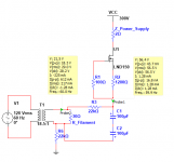
Here is my regulator. I used SY's approach of floating the ground on the heater circuit, and then lifting it using a simple voltage divider off the B+. The schematic is attached below.
H+ H- and HCOM are from the raw supply shown below.
This is a simple bridge rectifier with two 4700 uF caps, one for H+, and one for H-. The caps are referenced to HCOM, which is the transformer CT.
This is the same as the circuit shown in SY's HMN article (Figure 9). The only possible difference is that I connected the "ground" ends of the caps to HCOM. Figure 9 does not show a connection there, but it seemed logical, otherwise the "ground" is referenced back to the un filtered transformer CT.
Without a load the outputs of the heater V1+ and V1- are at 33.15 and 26.85 volts, so the filament voltage should be 6.3, raised 30 volts. This is all fine until I apply a load. When I do that I get ripple on the supply and that seems to go right through the regulators.
Is it possible that HCOM is changing depending on which direction the current flow is in the transformer, and this is effectively reducing the ability of the caps to filter? I am intrigued that Jackinnj's circuit appears to have two ungrounded back to back caps, so maybe that's the trick..
Attachments

Last edited:
Jackinnj had suggested that HCOM was modulating the regulators. I set up an experiment and compared HCOM (the elevated heater "ground") to ground, and to V+ and V- (the heater lines).
The suggested cap between HCOM and actual ground is there on the regular board, and it seems to be doing its job properly. The noise on HCOM relative to real ground is in the mV range. So, that's not the problem.
Here is HCOM at 2 mV/div.

Here are the heater lines (V+ and V-) It's hard to see the ripple, since this is DC coupled, and the scale in 10 v/div. However, you can see that the two signals are about 6 volts apart, and the ripple is anti phase (if it was common mode, then the balanced nature of the amp would reject it (not ideal, but not as much of a problem).

Here are the same signals AC coupled at 500 mV/div. I have separated the traces. They are exact anti-phase mirror images of one another.

I also tried disconnecting the two 4700 uF caps from HCOM (letting them float between H+ and H- (which is how they are inn SY's HMN diagram -fig 9). No difference at all.
I decided to try to narrow this down a bit. So, tested the raw supply with none of the regulators attached.
Here is H+ with no load. Flat as can be... About 6.5 volts.

I hooked up a 500 watt 8 ohm resistor I use for power amp testing to the H+ and H- lines, (this was with no regulator attached). This should pull about 800 mA, which is a tad more than we would see with two EC88 tubes.
Here are H+ and H- at 2 v/ div. You can see the ripple is about 1.5 volt!

So clearly the issue is in the super simple raw supply.
The suggested cap between HCOM and actual ground is there on the regular board, and it seems to be doing its job properly. The noise on HCOM relative to real ground is in the mV range. So, that's not the problem.
Here is HCOM at 2 mV/div.
Here are the heater lines (V+ and V-) It's hard to see the ripple, since this is DC coupled, and the scale in 10 v/div. However, you can see that the two signals are about 6 volts apart, and the ripple is anti phase (if it was common mode, then the balanced nature of the amp would reject it (not ideal, but not as much of a problem).
Here are the same signals AC coupled at 500 mV/div. I have separated the traces. They are exact anti-phase mirror images of one another.
I also tried disconnecting the two 4700 uF caps from HCOM (letting them float between H+ and H- (which is how they are inn SY's HMN diagram -fig 9). No difference at all.
I decided to try to narrow this down a bit. So, tested the raw supply with none of the regulators attached.
Here is H+ with no load. Flat as can be... About 6.5 volts.
I hooked up a 500 watt 8 ohm resistor I use for power amp testing to the H+ and H- lines, (this was with no regulator attached). This should pull about 800 mA, which is a tad more than we would see with two EC88 tubes.
Here are H+ and H- at 2 v/ div. You can see the ripple is about 1.5 volt!
So clearly the issue is in the super simple raw supply.
- Home
- Source & Line
- Analogue Source
- "Equal Opportunity" MM Pre