I have been digging this morning and remembering a bit as I got deeper in.
First, a caveat that shouldn't make any difference. I am using PCC88/7DJ8 tubes with a 7 volt heater for their perceived cost/value. Actually, they will run just fine on a 6.3V heater supply, but I made mine 7V or +/-3.5VDC just because.
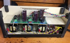
This was my first tube project, so I may have gone overboard on the power supply, but I will say that it is silent, so the difference in the raw supply may be the difference.
I am using 3 transformers. One for B-, one for the heaters, and one for B+. Overkill.
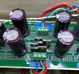
The transformers, diode bridge, and first stage of smoothing are in a separate box. The DC goes from that box to the main regulator where there is a resistance, followed by another capacitor. In other words, a split CRC filter. My first stage is two 4700 uF caps in parallel per rail. That is followed by a 1R Ohmite carbon resistor (my father parts box) and another 4700 uF. That feeds the HMN regulator with the heaters wired as you have, that is a single H common.
With the EO powered, the output of the first box is + and - 7.75 VDC with 180 mVAC. After the second stage of the filter and the regulator, the output is + and - 3.55 VDC with less than 1 mVAC.
As I did this, I remembered that I had originally started with a different heater transformer. I found that the heater drew down the voltage more than expected. A rough estimation of the transformer suggested something like 25% regulation which I hadn't counted on. The transformer I am using is a Triad VPS12-3400 that is a 43 VA, parallel 6.3V secondary EI transformer. The 7DJ8 heater is 7V, 300 mA, so the 3.4 rated amps is a bit overkill for the 1.2 amps draw of 4 heaters, but the headroom was needed to get things in the box, at least for me.
I hope this helps. Let me know if you need something else.
Jac
First, a caveat that shouldn't make any difference. I am using PCC88/7DJ8 tubes with a 7 volt heater for their perceived cost/value. Actually, they will run just fine on a 6.3V heater supply, but I made mine 7V or +/-3.5VDC just because.
This was my first tube project, so I may have gone overboard on the power supply, but I will say that it is silent, so the difference in the raw supply may be the difference.
I am using 3 transformers. One for B-, one for the heaters, and one for B+. Overkill.
The transformers, diode bridge, and first stage of smoothing are in a separate box. The DC goes from that box to the main regulator where there is a resistance, followed by another capacitor. In other words, a split CRC filter. My first stage is two 4700 uF caps in parallel per rail. That is followed by a 1R Ohmite carbon resistor (my father parts box) and another 4700 uF. That feeds the HMN regulator with the heaters wired as you have, that is a single H common.
With the EO powered, the output of the first box is + and - 7.75 VDC with 180 mVAC. After the second stage of the filter and the regulator, the output is + and - 3.55 VDC with less than 1 mVAC.
As I did this, I remembered that I had originally started with a different heater transformer. I found that the heater drew down the voltage more than expected. A rough estimation of the transformer suggested something like 25% regulation which I hadn't counted on. The transformer I am using is a Triad VPS12-3400 that is a 43 VA, parallel 6.3V secondary EI transformer. The 7DJ8 heater is 7V, 300 mA, so the 3.4 rated amps is a bit overkill for the 1.2 amps draw of 4 heaters, but the headroom was needed to get things in the box, at least for me.
I hope this helps. Let me know if you need something else.
Jac
Attachments
Before I pulled the EO out of the system to figure out the heater, I listened to Rickie Lee Jones. Her song "Easy Money" sounded just fantastic. Her voice and delivery, of course, but the attack of the mallets of the vibra-phone and the smoothness of the bass make it special. I still think this is a really good phono pre and it has never let the side down as I continued to improve my analog chain over the last couple of years.
Stick with it and keep massaging out those pesky problems. Its worth the trip.
Jac
Stick with it and keep massaging out those pesky problems. Its worth the trip.
Jac
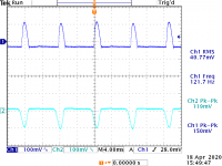
I did some figuring. The ripple is given by the following calculation:
Vr=I/(2FC), where C is in Farads.
Based on the cap values (4700 uF) and the current 750 mA, the ripple should be:
Vr=0.75/(120*.0047)=1.33 volts, so this actually seems to be working as designed. Not a very good design, but at least there don't appear to be any goblins lurking in the implementation.
I tried out some big 38K uF caps I had, and that cut the ripple down to about 0.25 volts (odd that it is not following the relation above..)
For fun, I tried putting a choke in series with H+. That pretty much killed the ripple >100 mV. The problem is, I have only one choke, and if I put it on H+. then the resistance of the choke throws HCOM off from a virtual ground. This is not a problem for the unregulated supply, but the regs relay on HCOM, and if one side has more resistance, the other will pul HCOM it that direction (which is what it did...).. I also put the choke in series with HCOM for fun. That significantly reduced the ripple, But it doesn't seem very efficient, since we then have a lot of interaction between the regulators because they then share a squishy virtual ground reference.
So, I think I'll get a couple of smaller chokes and add a second pair of 4700 uF caps following that. That's a much more efficient filter anyway.
Last edited:
I pulled up Duncan amps Power Supply Designer II and ran the numbers from my heater. It didn't agree with your equation, nor my measurements. I suspect, in the case of my measurements, a combination of unaccounted for wiring resistance and the meters interaction maybe involved once the ripple get somewhat low.
One question of curiousity. You are talking about an ECC88 pair at 750 mA. Do you have a separate heater for the second pair of tubes or do you have a different circuit after that. You probably already explained that, but I just missed it.
It looks like you got some direction, so best of luck.
Jac
One question of curiousity. You are talking about an ECC88 pair at 750 mA. Do you have a separate heater for the second pair of tubes or do you have a different circuit after that. You probably already explained that, but I just missed it.
It looks like you got some direction, so best of luck.
Jac
Did you look at the ripple on the 125V regulated line?
While each regulator sees 730mA or so load, they are also fighting to send current through the voltage divider -- the LM317 has about 65dB PSRR, the LM337 77 dB -- the 4700uF caps are a bit over the top.
I used SY's scheme in the HMN without issues.
The two transistor regulator which SY described in the LA article -- it's impedance is something like 2 ohms as I illustrated with a resistor in my prior post. Even a Maida will have impedance well less than an Ohm
Last edited:
I pulled up Duncan amps Power Supply Designer II and ran the numbers from my heater. It didn't agree with your equation, nor my measurements. I suspect, in the case of my measurements, a combination of unaccounted for wiring resistance and the meters interaction maybe involved once the ripple get somewhat low.
One question of curiousity. You are talking about an ECC88 pair at 750 mA. Do you have a separate heater for the second pair of tubes or do you have a different circuit after that. You probably already explained that, but I just missed it.
It looks like you got some direction, so best of luck.
Jac
Thanks Jac! I appreciate you taking the time to see what you did.
I think the key is the CRC filter. I think I'll try that. I was just researching coils, and finding a high current coil with reasonable inductance is tough, and expensive!
The E88 tube heater draws 365 mA, so with 4 tubes the supply needs to source 1.5 Amps.
Did you look at the ripple on the 125V line?
While each regulator sees 400mA or so load, they are also fighting to send current through the voltage divider --
I used SY's scheme in the HMN without issues.
The ripple on the 125 V line is near zero. I Have a 4 H choke on that with Caps on either side. So it is super clean. Good idea though.
I did some quick calculations.
With 1 ohm internal resistance, the bare 4700 uF filter cap will provide 12 dB of attenuation at 120 Hz .
In contrast, if I use the 4700 uF caps, and go through a 5 ohm resistor and then another 4700 uF cap, I get 45 dB of attenuation at 120 Hz.
The resistor will dissipate about 15 watts. I need to account for the voltage drop across the resistor. Turns out I can use the same transformer I started with on the HMN (18VCT). That produces an unregulated 13 volts at the 4700 uF caps (tried this using the existing circuit). Since I am aiming for about 6 volts at the regs (to get 3.15 out of each) a 5 ohm resistor in each leg will do the trick. Those are $3 ea versus $30+ ea for a coil.
I tried using an LM317/337 in an attempt to create an artificial ground for a headphone amplifier -- probably about 10 years ago -- what I found was that the regulators would pump each other owing to the small stimulus from the filtered V+/V-.
btw, C18, C19 are generally included when you want to knock down the noise of the LM317/LM337. High values cause slow transient response -- also results in slow startup time.
My HMN is in hibernation, will take it out and see what's the deal.
btw, C18, C19 are generally included when you want to knock down the noise of the LM317/LM337. High values cause slow transient response -- also results in slow startup time.
My HMN is in hibernation, will take it out and see what's the deal.
Stop press: I have been made aware that I posted an EO schematic somewhere in this thread with wrong parts values. I can't retract it, but please be aware that if you build this pre-amp, be sure to use the schematic and parts list from SY's Linear Audio Vol. 8 article.
Sorry for any issues this caused, my bad.
Jan
Sorry for any issues this caused, my bad.
Jan
Hmmm some of the cartridges particular the MMs have their cases shilded by one of the grounding pins (cold) on the back of the cart so if I want to make a "balanced" connection the shield should be separated! How do you cope with that kind of issues using the balanced phono? (Using MCs??) I like the goldring 1000 series and they have all this shild connected to green pin and looks its very hard to separate...Any thoughts, experiences?

Last edited:
You are correct, you need to remove or lift that ground connection on the cartridge. It’s very small.
The coloured rings come off quite easily, but the rest... You could cut the ring on one side to slide the ground off the pin.
Or
If they used the same body structure than my old 900IGC you could try to gently push off the 'ring' with the base (where you attach the cartridge to the head shell). This ring is normally glued, but might come off if you gently push between the pins while holding the ring.
Please be very careful and please don't hold it against me if something goes wrong 🙂
I have no experience with the Goldring 1000 series cartridges. All I can do is share thoughts and questions. What does the shield around the green pin connect to next? Do you need to eliminate it at the green pin or can you disable the ground connection somewhere else?
My build is finished! I didnt include the SS ccs just loding the tubes with a resisitors! The phono is very quiet just noticed that I have sone sort of high freq. noise in both channels, swaped the tubes no effect...has someone experienced similar? I will connect it to a scope to see what exactly is happening...otherwise the operation points are good B+ reg 180V B- reg -13.2V Heater 7V...
Congratulations! It's a good feeling to get it going.
My build was the standard design. I don't have any noise at all, dead quiet.
You might want to check the specs on your tube heater. I have seen 6922 datasheets where the heater spec is 6.3 +/-0.6V which would put your 7 volts at the top of the range. I have no idea if the noise you describe could come from the heater.
Jac
Congratulations! It's a good feeling to get it going.
My build was the standard design. I don't have any noise at all, dead quiet.
You might want to check the specs on your tube heater. I have seen 6922 datasheets where the heater spec is 6.3 +/-0.6V which would put your 7 volts at the top of the range. I have no idea if the noise you describe could come from the heater.
Jac
Thank you Jac! I dont think heater is a problem I am using 7V PCC88 tubes...I will have to connect it to a scope...Its a very quiet 6-10k tone maybe I am picking something up. Have to short the inputs to ground...
Cool! As it happens, I'm using PCC88 too. Mine are National (Matsushita) and they sound really nice. Which ones are you using and how do you find their sound character?
Jac
Jac
- Home
- Source & Line
- Analogue Source
- "Equal Opportunity" MM Pre