Are you sure you're in the correct thread?
EEPP = Equal Opportunity Phono Preamplifier
Using a SUT with the EEPP: see posts 24 & 25 in this thread
Sowter 1480 = Replaces the Sowter 8055X that is no longer being manufactured
D3A = tube that's use with the EEPP was first suggested in Pt. 1 of SY's articles (LA Vol. 7 Pg. 126)
I'm building a lot at the same time right now so my progress is going to be slow. Otherwise, yeah, I'm pretty sure in the correct thread.
yeah, I'm pretty sure in the correct thread.
Or to say it another way, you are building your own idea that is part way between "His Master's Noise" and "Equal Opportunity". I look forward to seeing how it goes.
Jac
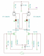
Here's an implementation which attains ~50dB of gain. If you've been watching Scott's 1000x amplifier thread, http://www.diyaudio.com/forums/grou...1000-low-noise-measurement-amp-ikoflexer.html you'll figure how the NFets gates are biased.
Attachments
Last edited:
Or to say it another way, you are building your own idea that is part way between "His Master's Noise" and "Equal Opportunity". I look forward to seeing how it goes.
Jac
Thanks! Not at all my own idea, just going off what SY has sugggested. I could still be completely wrong.
Jack, if you think I'm not going to get enough gain with my planned implementation, please just say it. I'm not exactly being coy about my inexperience here. But I can live with making mistakes, lord knows that's the only way I've learned anything so far.
Last edited:
Jack, if you think I'm not going to get enough gain with my planned implementation, please just say it. I'm not exactly being coy about my inexperience here. But I can live with making mistakes, lord knows that's the only way I've learned anything so far.
It won't be me suggesting implementation ideas. I'm probably more of a novice to tubes than you are. Guys like SY, Jackinnj, 6L6 and others have the experience and knowledge.
Jackinnj,
That's a pretty interesting schematic, similar to Eq Opp in some ways, except using Nfets and a pretty big capacitor in the signal path. Any idea how the noise level compares?
Jac
Will breadboard it and see!
Might be able to use active rather than passive RIAA compensation
how do you get 'EE' from 'Equal Opportunity'?
That's a very good question! Duly noted, to my everlasting embarrassment. 🙂
Just discovered this project. Not too many balanced phono out there. If someone has extra PCBs let me know.
Hi guys;
Jac just directed me to this thread.
I started building the HMN preamp, but quickly realized (fortunately before buying the Sowters) that I was going to use a MM cartridge..so I changed gears to the EO preamp.
There have been a few gear grinds in that shifting of gears...
I had already built the raw supply..and that had way too high a B+ level for the EO, so I had to order a new (special order) Edcor power transformer.
The raw supply seemed to work fine, so today I set up the regulator board.
I designed a new boards because I wanted a particular physical layout. So I have the signal stages on tow identical boards, and the regulators on a separate board. The signal boards have tube sockets on one side and components on the other, so the tubes can stick up though the chassis for ventilation, and esthetics. I built a teak chassis frame with mirror finish stainless panels to mount the boards. Here is a notional view of the partially finished setup.


The raw supply worked OK once I changed out the power transformer, but I also found that the heater supply for the HMN had too high an output voltage, so the LM317 and LM337 regulators were getting too hot and shutting down. I think a simple transformer change should remedy that.
I also discovered, too late, that the 3LM337 regulator pinout is different, so I'll have to do some surgery to fix that. Other than that, the build is coming along.
Here are the boards.
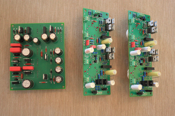
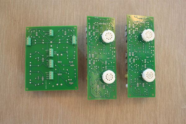
I did the signal boards separate from the regulator board. The reg board will be mounted vertically behind the vertical face of the chassis, so it will cool by convection. I can then run wires from the terminals on that board to the two signal boards.
I'll keep you all posted as the build progresses!
Scott
Jac just directed me to this thread.
I started building the HMN preamp, but quickly realized (fortunately before buying the Sowters) that I was going to use a MM cartridge..so I changed gears to the EO preamp.
There have been a few gear grinds in that shifting of gears...
I had already built the raw supply..and that had way too high a B+ level for the EO, so I had to order a new (special order) Edcor power transformer.
The raw supply seemed to work fine, so today I set up the regulator board.
I designed a new boards because I wanted a particular physical layout. So I have the signal stages on tow identical boards, and the regulators on a separate board. The signal boards have tube sockets on one side and components on the other, so the tubes can stick up though the chassis for ventilation, and esthetics. I built a teak chassis frame with mirror finish stainless panels to mount the boards. Here is a notional view of the partially finished setup.
The raw supply worked OK once I changed out the power transformer, but I also found that the heater supply for the HMN had too high an output voltage, so the LM317 and LM337 regulators were getting too hot and shutting down. I think a simple transformer change should remedy that.
I also discovered, too late, that the 3LM337 regulator pinout is different, so I'll have to do some surgery to fix that. Other than that, the build is coming along.
Here are the boards.
I did the signal boards separate from the regulator board. The reg board will be mounted vertically behind the vertical face of the chassis, so it will cool by convection. I can then run wires from the terminals on that board to the two signal boards.
I'll keep you all posted as the build progresses!
Scott
Scott,
Really nice casework! I can build a basic box, but nothing so pretty.
I also like the axial caps in the signal path. Radial caps are OK, but there are more choices available in axial, especially some of the bigger industrial caps.
I look forward to your progress.
Jac
Really nice casework! I can build a basic box, but nothing so pretty.
I also like the axial caps in the signal path. Radial caps are OK, but there are more choices available in axial, especially some of the bigger industrial caps.
I look forward to your progress.
Jac
Thanks Jac!
I have an old (1929) wooden boat, so I had to learn a lot about woodworking...
I got the stainless panels from Online metals.com. They will cut them to fit. I then drilled the holes for the tube sockets. The metal panes slide in to slots in the wood sides.
The axial caps are Mundorfs (and, I think, Vishay Roederstein). I haven't seen many audio quality radials.
Somewhat disappointed with the tube sockets (from Tube Depot), since the pin contacts are very very tight. I worry about breaking a tube getting it in or out.
There will be a perforated metal cage that slides into slots on the top and back to allow convection cooling of the regulator board (which mounts vertically behind the vertical steel panel.
But first to get the supplies working without lighting themselves on fire!
S
Last edited:
OK, got the heater supply sorted out. It turned out the transformer I was using had a second primary coil, so I connected the two primaries in series, and that dropped the raw DC output to about +/-6 volts. That then goes into the regs, and comes out at +/-3.15 volts for a full 6.3 across the two regs. The heater common is floating at about 20 volts.
Running two tubes, the 317/337 pair is at about 55 deg C with heatsinks, so I am hopeful that, running four tubes, the dissipation will not generate too much heat.
Next steps is to check out the CCS. I'll use Jac's trick of replacing the tube with a 10 K resistor to sort that out (clever idea!)
Cheers,
Scott
OK, got the heater supply sorted out. It turned out the transformer I was using had a second primary coil, so I connected the two primaries in series, and that dropped the raw DC output to about +/-6 volts. That then goes into the regs, and comes out at +/-3.15 volts for a full 6.3 across the two regs. The heater common is floating at about 20 volts.
Running two tubes, the 317/337 pair is at about 55 deg C with heatsinks, so I am hopeful that, running four tubes, the dissipation will not generate too much heat.
Next steps is to check out the CCS. I'll use Jac's trick of replacing the tube with a 10 K resistor to sort that out (clever idea!)
Cheers,
Scott
Scott,
Great news! Isn't it funny how something that seems to be simple, like a heater PSU, can take up your time and brain power?
As for 10k resistor instead of a tube, I can't take credit. SY or Jackinnj, or someone I can't remember suggested to me.
Jac
I spent part of today trying out the signal board with the regulator.
First thing I noticed was that when I went to hook up the VPP line, the voltage dropped from 125 to about 20. Hmmm. Farted around with that for a while and found that one of the VPP supplies was good, and the other wasn't (put a 10K load on each of the terminals and tested it that way. Turned out the collector on the pass transistor wasn't actually connected! (My board layout program can sometimes show a line over a pin, but not actually connected to the pin - surprised the DRC didn't find that). So a quick jumper fixed that, and now I seem to get a solid 125 v supply when hooked to the signal board.
I then found that I had forgotten to do the twisty dance with the LM337 leads (pins 2-3) for the negative 15V supply.. Once I did that, the negative supply worked (still only -12.5V because of the resistor error)..
So then I hooked up the signal board, and installed the 10K resistors. LEDs light, I get 64 volts at one plate pin and about 28-30 (depending on the trimmer resistor) at the other. Seems a bit low. The first "plate current" is 6.4 mA, and the second is under 3 mA.
I then found that the -15 volt supply was no longer at -15V. When it is connected to the signal board the supply droops to -2.5 V.. so clearly there is still something amiss in the negative regulators.
Time for a glass of wine...
Scott
Last edited:
Well, I sorted out the regulators today. I had somehow neglected to include the 200 uF caps on the -15 volt regulator outputs. Once I put those in and adjusted the resistors, the -15 volt supply is rock solid, and sits at -15.1 V.
So, I connected up the signal board, and set out to adjust the CCS. As noted above, the current in one leg was rather high. I traced this to an incorrect resistor value. When I first laid out this board I used some earlier version of the schematic and, apparently never corrected it, so one of the legs had a 100 ohm resistor, and the other had 620 ohms in parallel with the 5K pot and 5K resistor. Once I changed that to 560 ohms, the current were close (about 2.7 mA), and I was able to adjust them for a perfect match.
I then put in a tube and tried out the first stage.. Voila! we have gain!
I then repeated this on the second stage, and found, for some reason the current in the adjustable leg was too high. The resistor in that leg is intentionally higher than the other leg so it can be adjusted down, but 620 was too hot. So, I put in a 1K resistor in place of the 620, and was able to adjust the current to match.. again about 2.7 mA.
Seems odd that the resistor values want to be so different. I suspect this may be something in the FETs.
Doing a crude gain test, I get about 60 dB air 20 Hz, about 40 at 1KHz, and about 20 at 20 KHz, so this seems about right.
Next, I'll set up the other signal board, and get that sorted out.
Steady progress!
S
Last edited:
Hi Scott,
I think you should be congratulated. You are solving problems and progressing nicely.
Regarding the CCS resistors, if you didn't match the DN2540's, then I'm not surprised by the different resistors needed to achieve the desired current. Unless you get a tube of Mosfets from the same batch, they vary widely. The important thing is to hit your current target and you have.
Jac
Thanks Jac.
I was pleased at how quickly I got it all working once I sorted the regulators...
I had to order an unbalanced to balanced converter box (yeah, I could make one, but they are so cheap!) so I contest this with a true balanced input (I faked it for my initial signal tests). So tomorrow I'll tune up the other signal board, and then do some accurate tests...
Can't wait to hook it up to my turntable!
Scott
Jac;
I am a bit confused. It seems there are three different schematics for the EO preamp.
1) The schematic in the first installment of the article
2) The schematic in the second installment of the article (slightly changed component values)
3) The 10/27/14 PDF schematics. These include the grid resistors and still other component value changes.
I have not seen any drawings with resistors in the LED legs (not sure why these would be needed).
So which is correct?
Hi Scott,
It's a bit confusing isn't it. This was a case where things were changing over the time that articles were published and not everything got cleaned up. I was lucky to have SY around to answer questions. You are stuck with me. Sorry.
SY seemed to lean on the second article, Volume 8, and sometimes on the 10/27/14 pdf.
Regarding the grid resistors in the pdf. I confirmed with SY that they should be used, but the pdf schematic value is 10k and he told me 100R. Those resistors are labelled R51 and R52 in the boards I was working with. I apologize, I did say in series with the LEDs, but I meant the grid resistors. You are correct, no point in LED series resistors.
A difference between the V8 RIAA block and the pdf schematic, as explained in the article, is the use of a buffer before the RIAA filter or not. I followed SY's lead and built it without buffers (as in the article) and the 8.2k resistors in R14 and R15. Building it either way is fine.
In some ways, the pdf is confusing because it has the RIAA filter parts which aren't needed in the output stage. Of course, you do want the buffer in the output stage as shown in the article.
One other point. The output caps, C4 and C5 in the V8 article and pdf, need to be 200 VDC or higher because they see the B+ voltage. The caps in the RIAA, C2, C3, and C7, can be a lower voltage rating because they don't see the whole B+ to ground voltage. I mention this because it gave me more options for caps in the RIAA.
I hope I answered your questions. I admit, since it was more than a year ago, I had to scratch up my memory banks of some of this.
Jac
- Home
- Source & Line
- Analogue Source
- "Equal Opportunity" MM Pre