Well, the boards help make mistakes a bit tougher to do, thus my suggestion of 6CG7. The original SYclotron input stage from which this was derived used 6SL7, for what that's worth...
That's true. I'll certainly give it a go and it is probably a worthwhile comparison to do the ccs vs the choke load
I had a bit of time and started to assemble a breadboard -
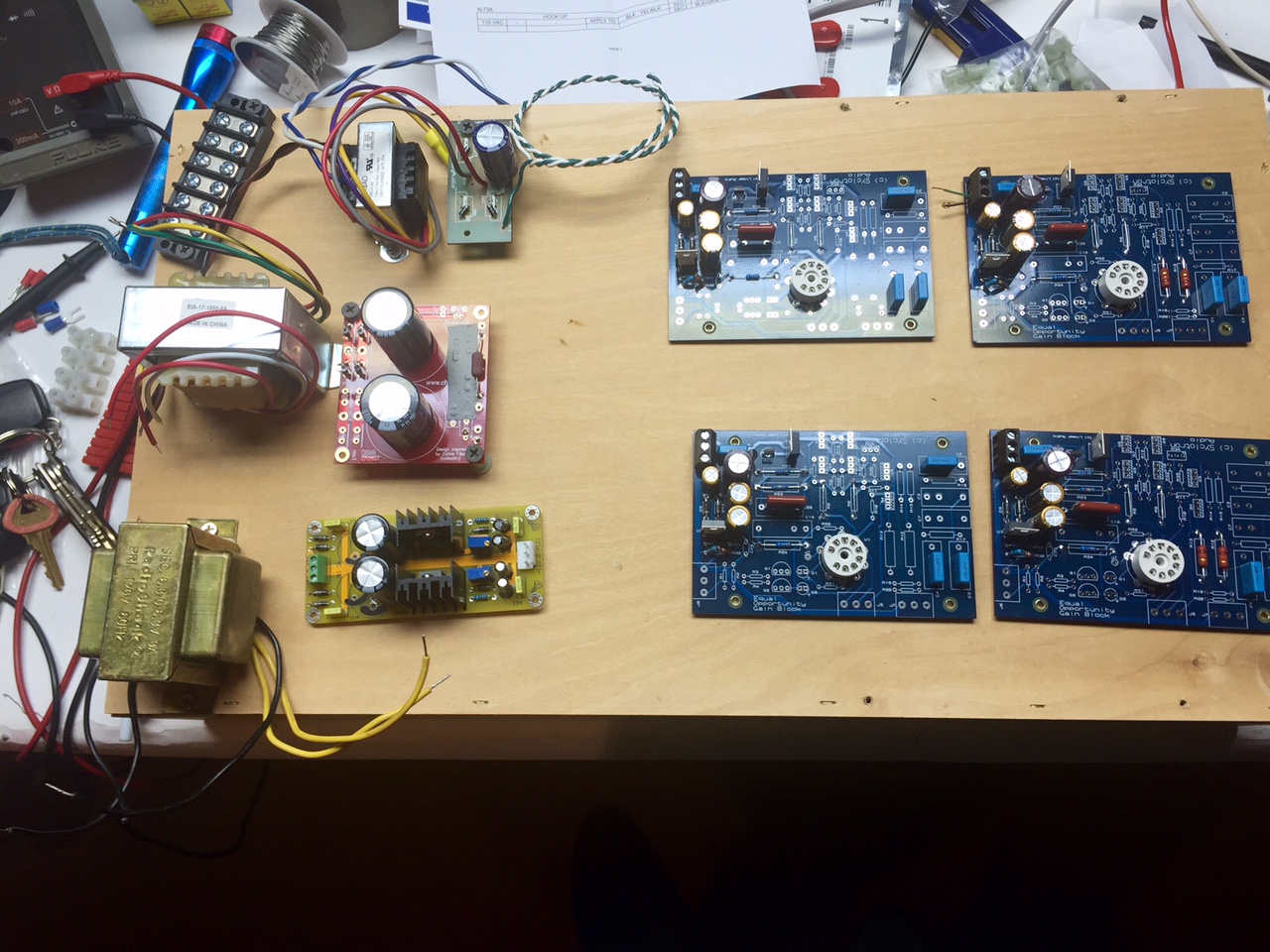
B- supply
B+ supply
Filament regulator
The B- is just a small transformer with a diode board snapped of an old diyAudio PSU board, with an 1000uF cap. The use of the (admittedly large for what it's holding) PCB is mainly because it has mounting holes, and can be attached to the chassis.
B+ also uses a PCB I had laying around, (hey, might as well use it, right? ) This time a chipamp PSU utilizing it's bridge and holes for snap-in caps, but the bipolar PCB is wired to be a single supply CRC. A bit crude perhaps, but again, it holds the diodes and caps nicely, and can be screwed into a chassis.
The filament supply I needed to order, it's an eBay special 317/337 PSU, that will be set for +/- 3.15V . The parts are probably all fake, but the PCB layout is actually pretty good. It will live in the chassis with the RIAA boards. (keep the regulators close to the load, as a wise man once said... 🙂 )
As of yet I haven't wired anything together nor tested the raw supplies. So far the only thing tested is the B- regulators, and they work fine. As lehmanhill noted, the set resistors (R30, R31) need a ratio of 11 to get the prescribed -15V, I changed the 1.2k to about 1.3k.
Nice progress.
I love the reuse of old project parts. I am always proudest of the projects where I can use all left over parts. Great job.
Jac
I love the reuse of old project parts. I am always proudest of the projects where I can use all left over parts. Great job.
Jac
Slowly accumulating parts for this project (have PCBs & tubes). Thinking ahead, I am wondering about the procedure for matching the pFets. Would something like this do the job sufficiently?: Testing and Matching JFETS | Stompville
It measures Idss and also measures Vgs at 10kOhm and Vgs(off) (technically, Vgs @ 10Megohm, which the documentation states is essentially the same thing). While it doesn't measure Gm, it can be derived using the equation: gm = |2 * (IDSS/VP) * [1 - (VGS/VP)]|
I guess the problem for me is knowing whether this device will provide me with all the terms needed for the equation.
Last edited:
A cheap DMM and a 9v battery is good enough - You could use a regulated bench PSU like I do, but the test is the same.
An externally hosted image should be here but it was not working when we last tested it.
That looks good for measuring Idss but I think we cross posted while I was editing to add more info. I thought I also need to match gm and to calculate that I also need Vp and Vgs or Id.
Last edited:
I'm hardly an expert, but I found Vgs to be a difficult thing to measure accurately. The slope near zero drain current is very low, so there isn't a good definition of 'off'.
Just for completeness, I did measure gm on my jfets, but they were all pretty close and Idss was the main thing I used for pairing jfets.
Jac
Just for completeness, I did measure gm on my jfets, but they were all pretty close and Idss was the main thing I used for pairing jfets.
Jac
Both of you, thank you. This is a brief overview in PDF form that I have been working off of:
http://www.kennethkuhn.com/students/ee351/jfet_basics.pdf
In LA Vol.8 pg.73 fig.12 SY graphs the spread of gm vs Idss for 17 LSJ74B pFETs (though the description says it's a group of 20). The gm varies from 20 to 26mmhos and the Idss from 6.1 to 10.5mA. Not sure how tightly matched these pairs ought to be but if we disregard gm then pairs are much easier to find within .1-.2mA of each other.
Anyone hear from SY since Nov. 10? I've been a bit concerned for over a month now.
Nope. Haven't heard from SY. Let's hope he is just busy with good things.
I had old Toshiba's, so it was not the same thing, but my matches were within 0.3 mA for the input boards and a little wider for the driver boards. If you can get 0.1 - 0.2 mA, my guess is you are plenty good enough.
Jac
Okay, from what I can tell the stompville JFET matcher I linked to earlier will work fine. Like Jac said, I could simply use a 9 volt battery and a fused DMM (set to measure D.C. mA) to obtain Idss. Applying that same 9 volts - but this time placing a 10 MegOhm resistor between the gate and source of the pFET and measuring the voltage across it - will essentially give me Vgs(off). For the sake of matching, Vgs(off) can effectively substitute for Vp and gm can be calculated using: −2Idss/Vp
Source: http://www.linearsystems.com/lsdata/others/JFETs_The_New_Frontier_Part1_by_Erno_Bordely.pdf
I hope this isn't too off topic but it was an obstacle for me in proceeding with this project and may be of use to others.
Source: http://www.linearsystems.com/lsdata/others/JFETs_The_New_Frontier_Part1_by_Erno_Bordely.pdf
I hope this isn't too off topic but it was an obstacle for me in proceeding with this project and may be of use to others.
Like Jac said, I could simply use a 9 volt battery and a fused DMM (set to measure D.C. mA) to obtain Idss.
I hope this isn't too off topic but it was an obstacle for me in proceeding with this project and may be of use to others.
First, 6L6 gets credit for the 9 volt battery suggestion, not me. But it is a good idea.
And this isn't off topic at all. I also matched my Mosfets. You have the choice of that or the extra balancing pot that SY suggested as an option. I found the Mosfets reasonably well matched when they were from the same batch. I ordered 25 and 21 of those were in the same tube and pretty close.
Enjoy the build.
Jac
First, 6L6 gets credit for the 9 volt battery suggestion, not me.
My apologies for not properly crediting you, 6L6.
Does anyone with Merlin Blencowe's JAES paper "Noise in Triodes with Particular Reference to Phono Preamplifiers" happen to know if it states the optimum operating current for a D3A tube? I have Merlin's Designing High Fidelity Tube Preamps but I'm not liking the results when I graph equation 5.21 on pg. 204, substituting the gm of a D3A (34) into the equation.
Last edited:
According to fm TavishDad's findings here, the average input-referred noise of a D3A at 7mA cathode current is 0.412uV (± 0.067). That's a good noise spec and as such seems like a good place to start.
Anyway, my EEPP is going to be for MC use (DL-103R). I already have a pair of Sowter 1480 SUTs (1:10) and plan on using D3As on the input boards and 6DJ8s on the output. Lots of reading ahead and lots of work. I still have a Lenco plus power supply and tonearm kit to assemble (audiomods) before I get to spin any records.
As might be apparent, this is just one part of a massive front-end overhaul.
Are you sure you're in the correct thread?
- Home
- Source & Line
- Analogue Source
- "Equal Opportunity" MM Pre