this is typical of all capacitor input filters fed from a rectified AC source.Even with just a 1.15A load the current through the diodes settles at 7A peak. Yes, there's the in-rush as the caps are charged but this appears to be within the peak limits. (The FFPF20UP40S have a non-repetitive peak surge current 60 Hz single half-sine wave absolute maximum rating of 200A while for the FFPF30UP20STU it's 300A, as I am sure you are already familiar with.) The one exception to this is the second wave through D4 but this would be below the repetitive peak limit of the 30A version.
It down to duty cycle. The charging current flows for about 5% to 20% of the sinewave cycle.
The heat in the diodes and the heat in the transformer and the heat in the capacitor all vary with I²R.
The pulsed currents result in MORE HEAT, even though the rms value of the current is relatively low.
LTspice models, analyses and graphs
https://dl.dropboxusercontent.com/u/70685392/Electronics/LT1084TL431-stability.zip
https://dl.dropboxusercontent.com/u/70685392/Electronics/LT1084TL431-stability.zip
Thanks Andrew. And so when I look at (modelled) current across C1 and C2 am I right to compare the peaks directly to the Rated Ripple Current of the filter caps?
If I set I2 to 5A these settle at 7.26A which is way above the 5.4A rating of the caps.
Also, I recognise that while the in-rush may be fine for the rectifier diodes, if the above is correct then the first few cycles are still a big problem for the filter caps and I'm going to have to come back to my questions regarding the DIYAudio soft-start board...
The long term average of the diode current waveform, must equal the long term average of the output current waveform. Since the diode current waveform varies between Ipeak and zero, while the output current is a very nice, smooth, constant 1.15 amperes .... Ipeak must be larger than 1.15 amperes in order to achieve a long term average of 1.15 amperes.
You can use calculus to integrate the diode currents {it's a built-in waveform arithmetic function in LTSPICE}, or if you prefer, you can approximate the current pulses as triangles, letting you use geometry instead of calculus. Either way you'll find that Ipeak > Iaverage. You'll also find that the ratio (Ipeak/Iaverage) increases as the filter capacitance is increased. This is one reason why some folks refuse to attach enormous filter capacitors to the rectifier diodes -- it keeps Ipeak manageable.
You can do a bit of fiddling around with the LT voltage regulator in its own little LTSPICE simulation, to discover whether the presupplied regulator model does, or does not, include current limiting. If you're inquisitive/skeptical you can do this twice: once with +9VDC input and 0.33 ohm output load resistor, and then again with a 0_to_9V input ramp and 0.33 ohm output load resistor. Thereby answering the questions (i) does it current limit in normal operation? (ii) does it current limit on startup?
Thanks Andrew. And so when I look at (modelled) current across C1 and C2 am I right to compare the peaks directly to the Rated Ripple Current of the filter caps?
If I set I2 to 5A these settle at 7.26A which is way above the 5.4A rating of the caps.
Also, I recognise that while the in-rush may be fine for the rectifier diodes, if the above is correct then the first few cycles are still a big problem for the filter caps and I'm going to have to come back to my questions regarding the DIYAudio soft-start board...
use PSUD2 to give you the rms current through the filter caps.
Don't use 100% of the ripple current rating.
That reduces the life to the specified 1000 to 2000hrs.
You want the ripple capability to be many times the ripple predicted by the model. This is what gives long life.
a transformer feeding rectified current into a smoothing capacitor has a filter that is effectively an rC.
The little r comes from the secondary resistance and the connecting wires resistances and the effective dynamic resistance of the diodes. This resistance limits the peak current. You can add a little bit more to lower the peak charging current.
The little r comes from the secondary resistance and the connecting wires resistances and the effective dynamic resistance of the diodes. This resistance limits the peak current. You can add a little bit more to lower the peak charging current.
SGK,
re post #74.
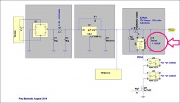
You need to have the mosfet switch after the regulator, else the system will never turn on. The TPS3510 supervisor will need to monitor the regulator output voltages (ie +12, +5 and +3) after the regulators, and if all are OK, then the mosfet switches are all turned on.
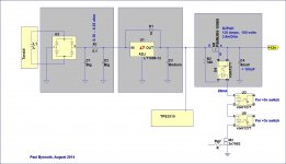
I suggest a circuit of the form attached. Note the following:
- Splitting the main capacitors (C1 & C2) into two and putting a small resistance between them helps to reduce the current charging pulses, and the regulator will see a little less ripple.
- C3 will be what ever the regulator requires (aprox 150uF).
- Put all the vom1271 input LEDs in series, then they all turn on and off at the same time, and run at 20mA to 25mA.
- Put each vom1271 close to their mosfet switch. The pin 4 to gate distance should be small (5mm), and the pin 3 to source distance less than 10mm if you can manage it. You don't need a gate resistor (if the above distances are small).
- The mosfet switch ideally would be a DPAK or To220 size device as the turn on current pulse will be high, which is why C4 needs to be small.
- The vom1271 will turn the mosfet switch on slowly (10s of millisecs) which is what you want in order to limit the current pulse from C3 into C4. The turn off time will be microseconds as the vom1271 has an internal fast turn off circuit.
regards,
Paul Bysouth
re post #74.
You need to have the mosfet switch after the regulator, else the system will never turn on. The TPS3510 supervisor will need to monitor the regulator output voltages (ie +12, +5 and +3) after the regulators, and if all are OK, then the mosfet switches are all turned on.
I suggest a circuit of the form attached. Note the following:
- Splitting the main capacitors (C1 & C2) into two and putting a small resistance between them helps to reduce the current charging pulses, and the regulator will see a little less ripple.
- C3 will be what ever the regulator requires (aprox 150uF).
- Put all the vom1271 input LEDs in series, then they all turn on and off at the same time, and run at 20mA to 25mA.
- Put each vom1271 close to their mosfet switch. The pin 4 to gate distance should be small (5mm), and the pin 3 to source distance less than 10mm if you can manage it. You don't need a gate resistor (if the above distances are small).
- The mosfet switch ideally would be a DPAK or To220 size device as the turn on current pulse will be high, which is why C4 needs to be small.
- The vom1271 will turn the mosfet switch on slowly (10s of millisecs) which is what you want in order to limit the current pulse from C3 into C4. The turn off time will be microseconds as the vom1271 has an internal fast turn off circuit.
regards,
Paul Bysouth
Attachments
The long term average of the diode current waveform, must equal the long term average of the output current waveform. Since the diode current waveform varies between Ipeak and zero, while the output current is a very nice, smooth, constant 1.15 amperes .... Ipeak must be larger than 1.15 amperes in order to achieve a long term average of 1.15 amperes.
This now seems frightfully obvious and I'm embarrassed by my earlier post in this regard
You can use calculus to integrate the diode currents {it's a built-in waveform arithmetic function in LTSPICE}
use PSUD2 to give you the rms current through the filter caps.
Thanks I will look at both. Glad it's not peak that I need to compare with the ripple rating.
You want the ripple capability to be many times the ripple predicted by the model. This is what gives long life.
Is there a useful 'rule of thumb'?
a transformer feeding rectified current into a smoothing capacitor has a filter that is effectively an rC.
The little r comes from the secondary resistance and the connecting wires resistances and the effective dynamic resistance of the diodes. This resistance limits the peak current. You can add a little bit more to lower the peak charging current.
Understood. I will have to take a look at the soft-start board again (and your comments re fusing both sets of primaries when using two transformers).
You'll also find that the ratio (Ipeak/Iaverage) increases as the filter capacitance is increased. This is one reason why some folks refuse to attach enormous filter capacitors to the rectifier diodes -- it keeps Ipeak manageable.
At least looking at the ripple ratings of the caps I was considering, it seems that ripple rating collapses with capacitance and so perhaps this is a bit of tail-chasing. I will have a look once I have done the above.
You can do a bit of fiddling around with the LT voltage regulator in its own little LTSPICE simulation, to discover whether the presupplied regulator model does, or does not, include current limiting. If you're inquisitive/skeptical you can do this twice: once with +9VDC input and 0.33 ohm output load resistor, and then again with a 0_to_9V input ramp and 0.33 ohm output load resistor. Thereby answering the questions (i) does it current limit in normal operation? (ii) does it current limit on startup?
will do
Thanks guys
How many times do I need to say it?..................
Understood. I will have to take a look at the soft-start board again (and your comments re fusing both sets of primaries when using two transformers).
................
Soft start for starting a transformer is different from slow charging for limiting the charging currents flowing into capacitors.
lots of smaller capacitors to make a bank of first stage capacitance gives the PSU a lot of ripple capability..............At least looking at the ripple ratings of the caps I was considering, it seems that ripple rating collapses with capacitance and so perhaps this is a bit of tail-chasing. I will have a look once I have done the above.................
That first capacitor is always the one that has to tolerate the worst ripple.
As for a rule of thumb: big enough that they never get hot. Heat severely shortens the life of electrolytics. Ripple through the ESR generates heat.
I don't know if that is 2times, or ten times, or 100times.
ClassB and ClassA will behave VERY DIFFERENTLY in the continuous and average ripple values seen by the first capacitor bank.
Last edited:
Hi Paul
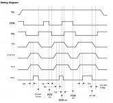
I think there are at least two core ways to skin this cat. I have attached the timing diagramme from the TPS3510 datasheet. Consider the following two 'triggers':
1. PSON/FPO Low with "switches" before regs.
Mains connected. 5VSB active/functioning. Main power rails' (12V, 5V, 3.3V) filter caps charge but their switch not yet on and regs are inactive. Switches (and VOM1271) need to be on the power rail boards rather than the TPS3510 board. (Rdson not an issue.)
When the motherboard sends PSON low, FPO goes low also. Power rail switches turned on by 5VSB and TPS3510 with FPO going low. Main power rails output voltages come up to spec. This is monitored by the TPS3510 (pins 5, 6, 7) and when they reach threshold voltages the TPS3510 sends PGO to the motherboard (with the requisite delay). Motherboard boots. (When PSON goes off/high, FPO goes high, switches close and the output caps should really be discharged.)
2. PGO with switches after regs. [This was indeed my original heading]
Mains connected. Main power rails come on, regs are active, output caps charge. Switches prevent flow to motherboard except for 5V to the 5VSB pin of the 24-pin ATX connector. Here the switches (and VOM1271) can be on the TPS3510 board with the ATX 24/12 connectors. Another big advantage is that there's no need for a 5VSB rail as all the power rails are on and 'available'.
Motherboard sends PSON low and FPO goes low as well (but doesn't trigger any switches). The main power rails are already at voltage and so PGO can be sent to the motherboard (after the requisite delay). PGO acts as a trigger to turn on the VOMs and power rail pass transistors. (When PSON goes off/high, FPO goes high, PSON goes low and the switches turn off power to the motherboard, except for 5V to the 5VSB pins of the 24-pin connector, although I note t4 in Fig 1 of the TPS3510 datasheet. Caps need only be discharged on mains disconnection.)
As previously noted, the second methodology was where I started until I became fixated on Rdson and current limiting. Most importantly, I thought that current limiting needed to occur before the regs to protect them (or prevent them shutting down). I now see the regulators' current limiting attenuates the current to acceptable levels ( a bit of 6A). As to Rdson, I agree that 1.8mOhms of resistance post regulators is trivial in the context of the wiring that follows. One might conclude that the first scenario is closer to the intended operation of a computer power supply while the second is more expedient (and cheaper).
This suggestion likely makes sense in either configuration. Thanks.
This is an area I have never really understood i.e. how large an output cap is required... Is the only consideration regulator circuit stability?
Agree re current and agree re in series if the second scenario above is followed. If the first then simply their placement on the power supply boards dictates the configuration I have used.
Understood. I had pin 3 to source less than 10mm but pin 4 to gate was more like 13mm because of the placeholder for a gate capacitor to manage Cload in-rush if needed (likely not). Advice applies to either scenario.
Why is C4 needed at all?
I made the jump to D2PAK during the safe harbour guidance discussion
I'm not sure I understand this. Fig 5 of the VOM1271 data sheet has turn on/off time versus diode current. T-on at 20mA looks more like 50 micro seconds.
Regards
Steve
You need to have the mosfet switch after the regulator, else the system will never turn on. The TPS3510 supervisor will need to monitor the regulator output voltages (ie +12, +5 and +3) after the regulators, and if all are OK, then the mosfet switches are all turned on.
I think there are at least two core ways to skin this cat. I have attached the timing diagramme from the TPS3510 datasheet. Consider the following two 'triggers':
1. PSON/FPO Low with "switches" before regs.
Mains connected. 5VSB active/functioning. Main power rails' (12V, 5V, 3.3V) filter caps charge but their switch not yet on and regs are inactive. Switches (and VOM1271) need to be on the power rail boards rather than the TPS3510 board. (Rdson not an issue.)
When the motherboard sends PSON low, FPO goes low also. Power rail switches turned on by 5VSB and TPS3510 with FPO going low. Main power rails output voltages come up to spec. This is monitored by the TPS3510 (pins 5, 6, 7) and when they reach threshold voltages the TPS3510 sends PGO to the motherboard (with the requisite delay). Motherboard boots. (When PSON goes off/high, FPO goes high, switches close and the output caps should really be discharged.)
2. PGO with switches after regs. [This was indeed my original heading]
Mains connected. Main power rails come on, regs are active, output caps charge. Switches prevent flow to motherboard except for 5V to the 5VSB pin of the 24-pin ATX connector. Here the switches (and VOM1271) can be on the TPS3510 board with the ATX 24/12 connectors. Another big advantage is that there's no need for a 5VSB rail as all the power rails are on and 'available'.
Motherboard sends PSON low and FPO goes low as well (but doesn't trigger any switches). The main power rails are already at voltage and so PGO can be sent to the motherboard (after the requisite delay). PGO acts as a trigger to turn on the VOMs and power rail pass transistors. (When PSON goes off/high, FPO goes high, PSON goes low and the switches turn off power to the motherboard, except for 5V to the 5VSB pins of the 24-pin connector, although I note t4 in Fig 1 of the TPS3510 datasheet. Caps need only be discharged on mains disconnection.)
As previously noted, the second methodology was where I started until I became fixated on Rdson and current limiting. Most importantly, I thought that current limiting needed to occur before the regs to protect them (or prevent them shutting down). I now see the regulators' current limiting attenuates the current to acceptable levels ( a bit of 6A). As to Rdson, I agree that 1.8mOhms of resistance post regulators is trivial in the context of the wiring that follows. One might conclude that the first scenario is closer to the intended operation of a computer power supply while the second is more expedient (and cheaper).
I suggest a circuit of the form attached. Note the following:
- Splitting the main capacitors (C1 & C2) into two and putting a small resistance between them helps to reduce the current charging pulses, and the regulator will see a little less ripple.
This suggestion likely makes sense in either configuration. Thanks.
- C3 will be what ever the regulator requires (aprox 150uF).
This is an area I have never really understood i.e. how large an output cap is required... Is the only consideration regulator circuit stability?
- Put all the vom1271 input LEDs in series, then they all turn on and off at the same time, and run at 20mA to 25mA.
Agree re current and agree re in series if the second scenario above is followed. If the first then simply their placement on the power supply boards dictates the configuration I have used.
- Put each vom1271 close to their mosfet switch. The pin 4 to gate distance should be small (5mm), and the pin 3 to source distance less than 10mm if you can manage it. You don't need a gate resistor (if the above distances are small).
Understood. I had pin 3 to source less than 10mm but pin 4 to gate was more like 13mm because of the placeholder for a gate capacitor to manage Cload in-rush if needed (likely not). Advice applies to either scenario.
- The mosfet switch ideally would be a DPAK or To220 size device as the turn on current pulse will be high, which is why C4 needs to be small.
Why is C4 needed at all?
I made the jump to D2PAK during the safe harbour guidance discussion
- The vom1271 will turn the mosfet switch on slowly (10s of millisecs) which is what you want in order to limit the current pulse from C3 into C4. The turn off time will be microseconds as the vom1271 has an internal fast turn off circuit.
I'm not sure I understand this. Fig 5 of the VOM1271 data sheet has turn on/off time versus diode current. T-on at 20mA looks more like 50 micro seconds.
Regards
Steve
How many times do I need to say it?
Soft start for starting a transformer is different from slow charging for limiting the charging currents flowing into capacitors.
Only once. First I have heard this statement. Apologies if I missed it before.
the charging current is related to the emf available from the transformer secondary and the total resistance (if we are looking at DC currents) or total impedance (if we are looking at changing currents).
I'm no good at the AC theory so I usually simplify (actually oversimplify) to considering instantaneous DC current.
I look at peak voltage and total resistance to work out the worst case peak charging current.
Ipk=Vpk/R
At the instant that we connect the capacitor to the rectifier (with the transformer already started) we get that enormous initial charging current. That damages a capacitor forever. Don't do it.
Similarly shorting an already charged capacitor damages a capacitor forever. This effect is usually worse because the total resistance is lower.
But this is worst case.
In practice we have the capacitors connected as the transformer starts and the secondary emf builds rapidly, but NOT instantaneously. That slower being to the charging lowers the initial peak current.
Maybe half the worst case from earlier, maybe a lot less than that worst case.
But it's what we do. We switch on at the mains with the capacitors already connected.
I suggest a circuit of the form attached {copied below --MJ}
Paul, there's a pretty good chance that the +12V output rail, the +5V output rail, and the +3.3V output rail are all connected to an ATX-formfactor motherboard, for a personal computer. The motherboard contains bypass capacitors on each of these rails, which are larger than your recommended "C4" value.
If this is the case, then there is an inrush current event when the MOSFET turns on. To take one phony-baloney, made-up, hypothetical example, when the +12V rail turns on, if its total rail bypass capacitance is 20,000 microfarads, and if its gate ramps up in 50 milliseconds ("tens of milliseconds" as you call it) then C=0.02, deltaV=12, deltaT=0.05, and I_inrush = (0.02 * 12 / 0.05) = 4.8 amperes. During the initial segment of the turn-on waveform, the MOSFET has 12V on its drain and <1V on its source, so power dissipation is 11V x 4.8A = 52.8 watts. Maybe too much for small-die MOSFETs having puny thermal pathway from die-paddle to PCB heat spreader. Maybe it violates the datasheet "Safe Operating Area" by a frighteningly huge amount.
Attachments
Last edited:
Ok this has been very helpful. I have been looking at various cap and resistor configurations in LTspice, the RMS currents through the caps etc. (The RMS calc in LTspice is very handy!) A lot of things now make much more sense.
What would be considered very good quality caps suitable for this type of application? (i.e.brand, product line etc). I was planning to use 25V Mundorf A-Lytic capacitors. Why? For no other reason than I already have three, they seem to be well-regarded and perhaps, admittedly, because they have that 'Stella Artois factor' ("reassuringly expensive"...a UK advert... Google if unfamiliar). 🙂 😱 I'm open-minded to quality alternatives.
Juggling the number of caps, footprint, capacitance per cap and ripple ratings seems to be a bit of an art.
If, for example, I were to consider a configuration with 3 filter caps - cap, cap, 3x0.47R resistors, cap - normalised RMS currents for the caps at full 5A load (looking at 5V power rail only at this stage) are 2.9A/2.9A/1.7A for 10,000uF caps and 3.2A/3.2A/1.4A for 22,000uF caps. Yet the higher capacitance Mundorf caps have a ripple rating of 5.4A versus 3.2A for the smaller ones. The 10k caps also have ESR of 32mOhms versus 14mOhms for the larger ones and have only a slightly smaller footprint.
Calculating temperature rise of an electrolytic cap. I can use LTspice to model the power dissipated by a capacitor. For example, for normalised operation (i.e. post initial in-rush) with full 5A load integrating the power wave form suggests a dissipation for the first 10,000uF capacitor of 2.7W. I'm trying to see what this means for temperature rise. Am I right to look at the Mundorf data sheet, note Tmax = 125C, note 'Rated Ripple Current at Tmax and 100Hz' = 3.2A and perform the following calculation?
rise in temp = (125-25) x (2.9^2)/(3.2^2) = 82C
It would seem to make sense - as it would be operating close to its Ripple Current limit the temperature of the cap rises close to it's maximum (i.e to a temp of 107C given a 25C room temp). At this temp the cap would have a Useful Lifetime of c8,000 hours and a Rated Lifetime of 2,000. I'm not sure what the difference is between the two but neither are great when one considers I usually leave my audio server permanently on. (I probably need to reconsider this.) The equivalent temp rise calculation (if this is correct) for the larger capacitance caps is 35C leading to much longer lifetime.
Regards
Steve
You could consider putting an inrush current limiter in series with the power transformer's primary. (Here are some datasheets of the ICLs that Nelson Pass routinely uses in power amplifier designs).
This would limit inrush current AND it would provide a series resistance that limits rectifier current / filter capacitor current. You can work out the equivalent secondary resistance, given a certain resistance in the primary, using the transformer equations. OR you can just run a few simulations with, and without, the at-high-temperature series resistance in the primary. I'm guessing that SGK's ATX motherboard application probably draws about 100 watts from the DC supplies, and the regulators probably operate at about 50% efficiency, so that's about 200 watts drawn from the 230VAC mains. Maybe a CL-80 or a CL-90 would be a decent choice.
Caveat: this is an unpopular design choice. Practically zero DIY designs use it, and very few commercial designs use it for such a low VA-rated transformer. Let the nonconformist beware.
Last edited:
Thanks Mark. I guess this begs the question of "why is it an unpopular design choice?" Presumably the challenge of in-rush through rectifier diodes to charge a bunch of filter caps is a common design challenge. I'm not sure why my case is 'special'.
In addition to the two questions in post #96, I would be grateful if someone could answer the question in the PS to post #72. The latter will help when I finalise the cap arrangement and get to revising the board layout for the power rails.
In addition to the two questions in post #96, I would be grateful if someone could answer the question in the PS to post #72. The latter will help when I finalise the cap arrangement and get to revising the board layout for the power rails.
DIYers don't use NTC thermistor Inrush Current Limiters, because the schematics they are copying-and-modifying, don't include ICLs. In other words, they're out of fashion now because they were out of fashion last year. And in turn, they were out of fashion last year because they were out of fashion two years ago. Repeat sixty times.
D. Self includes a few pages in APAD6ed, explaining why he prefers other circuit approaches instead of ICL thermistors, to limit inrush current. Personally I find one of his reasons, "service personnel safety," decidedly unconvincing. John Curl's Parasound HCA-1000, of which I own two units, tucks its ICL thermistor away safely in a fiberglass insulating sleeve, in the bottom front corner of the chassis, far away from inquisitive fingertips.
Fear Of Heat is probably also the reason why National Semiconductor's application note AN-1849 (snaa057b), avoids an ICL and instead uses a soft start circuit having 9 components (!). It's more expensive, it take up more board area, but it runs cool.
Bob Cordell has a discussion of ICLs as well.
The idea of limiting diode peak current in normal operation, long long after startup, by installing a series resistance between the trafo secondary and the diode bridge, appears to be considered blasphemous heresy. No one does it and no one thinks about doing it. Moving this blasphemous resistor into the transformer primary circuit instead of the secondary, apparently adds treason to the indictment. Right thinking people say no, hell no. Let the nonconformist beware.
Ok I am trying to stitch together your comments and Andrew's "how many times do I need to say it" comment. It would seem to me that while they are two different components they are, combined, the same problem. When mains power is connected, the transformer needs to energise and the caps charge. As Andrew notes later, because the transformer isn't fully energised at turn-on the in-rush to the capacitors is slowed by the energising of the transformer (versus connection of caps to an already charged transformer) and so the energising of the transformer helps alleviate the cap charging problem. Surely, slow the in-rush into the transformer and you also slow the in-rush into the caps? Tackle this with a soft-start circuit a la the DIYAudio soft-start board, AN-1849's circuit or an NTC thermistor in-rush current limiter. Maybe I am missing something but they're the same design challenge. Perhaps people assume the cap charging isn't an issue because it is slowed by the transformer energising and hence just focus on slowing the energising of the transformer.
I was planning on having two transformers. One for the 5V and 3.3V supplies (dual secondaries) and another for the 12V supply (single secondary). I haven't selected the transformer yet but the supplier I was considering appears to provide 10V secondaries minimum (unless a special order) and so would have plenty of voltage headroom. (Hence you saw 14.14V DC in my 5V circuit PSRR/transient analyses. I should have subtracted a couple of diode drops but given potential variance in the 230VAC side I didn't bother at this stage.)
I guess a 100VA for the 3.3/5V supplies would provide plenty of headroom (?). (If anyone has views on this supplier I would appreciate it.)
For the 12V supply I will need a higher output voltage if I use the regulator I have here already (rather than the circuit shown for 5V). It has a 4V drop. Perhaps 120VA would be about the right size? Overall, not massive transformers like those one might see in a power amplifier.
Modelling transformers in LTspice when once doesn't know their inductance etc is guess work but maybe I will simulate a transformer with some assumptions and see what it looks like.
- Status
- Not open for further replies.
- Home
- Amplifiers
- Power Supplies
- Enough current to turn on 3 mosfets?