Doug, to your point it is the applications that are different.
Exactly, the reactance behaviour is exactly the same, as is the math, it's just a matter of how we're using it...
You may find some helpful insight or at least a good review at All About Circuits The AC circuits section will probably interest you the most.
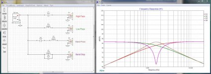
I'm adding a DXO file for XSim that will let you easily explore the fundimental types. Most crossovers are simply combinations of these filters. You can selectively enable one filter at a time, mess with the parts values and see what they do.
Attachments
Last edited:
Maybe a half octave more than that..At 50 y/o what the tweeter does beyond 10 kHz is really not going to matter anyway it would seem.
I see what you are getting at Doug. Yes, things like harmonic filters or blocking filters for vfds would follow the exact same theories and calculations. What I mean to say is I have never done that type of work, I have always used capacitors connected in parallel and not series so this area is essentially new to me. The calculators will be handy once I get something built and want to contemplate making a change. The circuits Earl provided are therefore essential to give me something to build on. I can the tweak later if desired.
Question for Earl or Allen:
That parallel circuit to the 4.7 ohm attenuation resistor that is centered around 10 kHz, is that necessary for a new tweeter? I see Earl has it carried over. My initial take on it was it was there to compensate for the tweeter design but since it is carried over is it seen as something to help any given aluminum dome tweeter mesh with the aluminum dome mid frequency driver. I think Allen mentioned working around a resonance point in one of his posts.
Earl and I each suggested different possibilities. One was regarding some breakup modes. This is a mechanical issue with the dome which can sometimes be partially compensated electrically. I think you'll find that this is not expected to be an issue with many tweeters to the point that you would remove that circuit when replacing the tweeter.. unless you find evidence that it would be helpful to replace it. They all breakup but it isn't always an issue.
The other was the designer dealing with a rising response. Again this isn't normally to be expected. Sometimes this happens not for natural reasons but when you are designing the crossover.. and when that happens to me I will typically take a step back and find a new approach to the circuit rather than using tank circuits.
So yes, probably don't use it. Some aluminium domes have been known to sound like a piece of foil, I wouldn't put them all in this basket.. Also sometimes a series resistor is bypassed by a capacitor to increase the highs by a gentle curve, this is obviously not really the same as a resonant circuit.
I see what you are getting at Doug.
With respect ... I don't think you do.
Earl's circuits are drawn in XSim, using very complex crossovers. Unless you start with the most basic use of the components as I described, you are going to be unable to adjust those designs for your needs. I was merely suggesting that you engage in a proper learning curve ... It is always a good idea to see if there's water in the pond before diving in head first.
One of the big problems with speakers right now is that crossovers are slowly becoming less and less efficient and more and more complex. (and, yes, those two facts are related). In some cases it is obvious the designer was playing with XSim (or one of the other CAD tools) like it's a video game, just tossing stuff in until he manages to hammer the thing into shape. In fact many of the crossover designs you see here are mostly a matter of dumb luck with no real electronic skill behind them ... and it shows.
Now don't take this the wrong way. There are some gifted people here and they do very good work.
My point is that you need the requisite understanding to know the difference.
Going back to your original reason for being here ...
You have two tweeters that are blown. Don't get too far off mission. It's fun to discuss all this other stuff, but that isn't getting your speakers back in service and it's not likely to be all that helpful when you do.
Concentrate on finding suitable replacement parts. Get them installed and see what you get.
You might be very pleasantly surprised.
Also, as I pointed out early in this thread, you may need to think about your amplifier too. Those are power hungry speakers and you do need to think about not blowing the tweeters again.
Last edited:
Douglas said:Going back to your original reason for being here ...
You have two tweeters that are blown. Don't get too far off mission. It's fun to discuss all this other stuff, but that isn't getting your speakers back in service and it's not likely to be all that helpful when you do.
Concentrate on finding suitable replacement parts. Get them installed and see what you get.
Good Advice!
🙂
Ok Allen, that is what I wanted to confirm. Since I don't see that parallel circuit in any other crossover design so I have to question why I should make it necessary to address a specific frequency of a replacement tweeter, unless it was to address something I don't understand.
As I understand it, I can put some new tweeters in, eliminate that bypass circuit and, in doing so, start with a lower series resistor of say 2 ohm instead of 4.7 ohm and that resistance would be my first item for "tuning" without using software. Looking at either the SB that Earl suggested or the Seas that Chris at Solen suggested. Chris suggested that the Seas is a good choice since it should work well with the crossover drawing I sent him.
I believe if I do the above then I am staying with the basics of getting my speakers working. If I start playing with a design program, ordering all new capacitors, inductors and resistors to build an entirely new crossover for the tweeters based on a computer program then I am very far from the basics.
Just to revisit the part about the amplifier, yes I understand that and already have responded to that point. I have been in discussion with Zed Audio about it as they are the original builders of the amplifier.
Ken,
That HF ( frequency dependent ) bypass circuit is very useful for fixing HF problems that are present in many tweeters ( particularly in their off-axis response ).
- Addressing those anomalies can help the drivers overall power response ( which is like an average taken across a few angles ).
Without seeing the raw response of your original tweeter, one can only speculate as to it's deficiencies ( considering the network designer threw the "kitchen sink" at it ).
As I mentioned before > look at the off axis response ( from the different manufacturers ) to get an idea of the amount of perceived top-end .
There's a huge difference ( using this metric ) when one compares the SBA and the much cheaper Peerless ( the two I recommended you buy ).
BTW, in XSim, when a part's value is blank ( ;ie; an area of nothingness > instead of showing a value ) that means that part is not in use ( out of circuit ) .
- That translates into the complete HF bipass circuit not being used with the SBA tweeter.
- If the part has a black line ( instead of a value ) the part has been bypassed by a piece of wire.
🙂
I see this is getting way off the rails...
Ok... here's how I would handle the situation, as a service tech.
I would look at the specs for your speakers and select a tweeter that has a similar frequency response, sensitivity and power handling.
I would order them in and then come to your home with them.
I would install them as a pair in both your speakers.
I would run a couple of gated close mic scans with REW to confirm they're not way out of whack.
You would pay me and I would go home.
I absolutely would not touch your crossover without good reason to do so.
(Rule #1: If it ain't broke don't fix it.)
Ok, real simple question ...
Your speakers are rated for 80 to 250 watts.
Does your amplifier's power output fall within that range?
It's just not that complex, my friend.
I believe if I do the above then I am staying with the basics of getting my speakers working. If I start playing with a design program, ordering all new capacitors, inductors and resistors to build an entirely new crossover for the tweeters based on a computer program then I am very far from the basics.
Ok... here's how I would handle the situation, as a service tech.
I would look at the specs for your speakers and select a tweeter that has a similar frequency response, sensitivity and power handling.
I would order them in and then come to your home with them.
I would install them as a pair in both your speakers.
I would run a couple of gated close mic scans with REW to confirm they're not way out of whack.
You would pay me and I would go home.
I absolutely would not touch your crossover without good reason to do so.
(Rule #1: If it ain't broke don't fix it.)
Just to revisit the part about the amplifier, yes I understand that and already have responded to that point. I have been in discussion with Zed Audio about it as they are the original builders of the amplifier.
Ok, real simple question ...
Your speakers are rated for 80 to 250 watts.
Does your amplifier's power output fall within that range?
It's just not that complex, my friend.
Last edited:
Douglas said:I would look at the specs for your speakers and select a tweeter that has a similar frequency response, sensitivity and power handling.
I would order them in and then come to your home with them.
If you know how to find out that information, then please post it ( I believe Ken has exhausted that route ).
🙂
I will go with the SB 26ADC tweeter you suggested Earl, as you say peoples reviews of them are quite good vs the Seas 27TBFC suggested by Solens which is difficult to find good opinions on.
To Doug's point, yes I would like to start with not modifying the crossover however if I find the replacement tweeter too forward or laid back initially I can see how to adjust that for an initial change. After that I can get into xsim and and start working with it and see where i could go from simply making the existing crossover work vs possibly building a new hf crossover section and put it in a package external to the speaker. That would all come later. And Earl provided a design that would be a basis for me to reference and check my work if I go down that road. However I do like simpler vs complex and so I do like the idea of removing that HF bypass circuit and therefore would do so and that would mean anticipation of a change in the 4.7 ohm resistor since a parallel path is being removed.
As for the amp question, yes my preferred unit fits that criteria. And until it is back in my system I am running what I have now that would otherwise be in the closet.
Ken,
A working example ( of when to possibly use the ByPass circuit ).
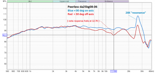
Here are the 00-degree and 30deg off-axis traces ( raw response ) for the ( inexpensive ) Peerless tweeter.

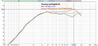
Now here's an HiPass example of the LCR bypass in use.

The LCR in the HF bypass has been modified to specifically fill the 12.7K hole ( this treatment also gives a rising response on axis as seen in the blue trace above the orange ).
Neither the SB Acoustics tweeter or the SEAS 27TBFC ( recommended by Chris ) benefit by the inclusion of this circuit.
A working example ( of when to possibly use the ByPass circuit ).
Here are the 00-degree and 30deg off-axis traces ( raw response ) for the ( inexpensive ) Peerless tweeter.
Now here's an HiPass example of the LCR bypass in use.
The LCR in the HF bypass has been modified to specifically fill the 12.7K hole ( this treatment also gives a rising response on axis as seen in the blue trace above the orange ).
Neither the SB Acoustics tweeter or the SEAS 27TBFC ( recommended by Chris ) benefit by the inclusion of this circuit.
Attachments
Ken said:I will go with the SB 26ADC tweeter you suggested Earl,
To Doug's point, yes I would like to start with not modifying the crossover however
Based on the above quote ( buying the SBA would be a mistake if you are not going to create a custom HiPass for it );
You're better off going with the SEAS as recommended by Chris at Solen.
The SEAS is a lot closer to acting as a drop in replacement ( than the SBA tweeter is ) once when one limits ones-self to only performing minimal mods on the original HiPass circuit.
XSim ( simulations ) indicate that you should disconnect the HF bipass circuit ( disconnection of the 910hz resonance circuit is optional ) .
Then you can focus on adjusting the value of that 4.7 ohm resistor to get a tweeter level you like.
🙂
Last edited:
If going that way, I'd begin by calculating the frequency of the series RLC across the driver, and comparing to the resonance of the new driver, decide whether to leave it, modify it or disconnect it. If it runs (significantly) at the wrong frequency it could be doing more harm than good.As I understand it, I can put some new tweeters in, eliminate that bypass circuit and, in doing so, start with a lower series resistor of say 2 ohm instead of 4.7 ohm and that resistance would be my first item for "tuning" without using software.
Then yes, play with the series resistance. However after this, the damping of the high-pass filter may have changed causing an issue around the crossover frequency.
To Doug's point, yes I would like to start with not modifying the crossover however if I find the replacement tweeter too forward or laid back initially I can see how to adjust that for an initial change.
Just one more note of caution...
Whatever you put in there is almost certainly going to sound different. Unless it is WAY out of line, don't go pulling things all apart. Give it a week or two for you to get adjusted to it... You might actually like the new sound once you are past reacting to the difference.
Of course, if it's just way way off... well, then the fun begins.
That is the truth of the matter Doug. I have lots to think about and understand why the xSim is mentioned.
Up till a little while ago I assumed speakers have an infinite life. Not sure that is true as it pertains to ferrofluid filled tweeters after 25 years. Wondering if there is a roll off with age, or drift within the crossovers. I have been blaming my other equipment but the speakers themselves may be suspect, or my own hearing.
I will consider the two options provided. The Seas and the SBA. I may choose the Seas route for the following reason:
It may be time to invest in new speakers.
I could go the Seas route, not tinker too much with the crossover but get them working well enough that I like the sound (since that is subjective) and then sell them and purchase something new. This was not even in my thinking since I was happy with the sound at one time and figured it would always be the same year after year. Perhaps that is not true and with anything old, they need some TLC/maintenance.
Conversely I could keep them long term and start pursuing a path of restoring the overall sound including a rework of the crossover to match a less compromised tweeter like the SBA. I was looking at the 3" aluminum dome midrange and how I deal with that in the future and that may be more problematic.
Lots to consider. Appreciate you guys walking me through this all. At this moment I am thinking that, as much as I like the Veritas, perhaps I should lean towards a path where I plan to buy a set of speakers and see if I can not only get back what I remember in the Veritas, but find something that excels with a unit of comparable MSRP. But what i think next week may change, depends how much I want to tinker with what I have now.
Thanks for those simulations Earl, they are definitely key pieces to shaping my thinking on how I approach a short term and long term solution.
That is the truth of the matter Doug. I have lots to think about and understand why the xSim is mentioned.
XSim is a simulator ... your results may vary. But in any case you need to know how to make basic adjustments of the parts, which is why I put up that basic filters example for you to play with. You need to know what you are doing when you change a coil or a cap or a resistor... and why. Otherwise I can pretty much guarantee a less than optimal outcome... worst case, you end up killing an amplifier. (And yes, that does happen)
Up till a little while ago I assumed speakers have an infinite life. Not sure that is true as it pertains to ferrofluid filled tweeters after 25 years. Wondering if there is a roll off with age, or drift within the crossovers. I have been blaming my other equipment but the speakers themselves may be suspect, or my own hearing.
None of this stuff has an infinite life ... especially our ears.
Speakers, in particular are not a fixed item, like an amplifier circuitry. They are mechanisms, transducers that turn electrical signals into movement of air. What you are actually dealing with is a linear position servo that moves a piston to a position dictated by the voltage across its terminals. Thus it is a machine, subject to the same wear and tear issues as any other mechanism.
Anything pushed to it's limits will fail more quickly. If you are listening at high enough levels to fry your tweeters, it is very likely that wear and tear is far more exaggerated than the designers would anticipate. Thus the mean time between failures is going to be drastically reduced. For loud listening --90+db-- you can expect no more than 6 or 8 failure free years from an average set of speakers. At more reasonable levels --50 to 60db-- that can increase to 20 or more years. (Same for your ears, btw)
Amplifiers generally have very few moving parts and thus can be expected to both last longer and keep their basic characteristics better. Except for the odd catastrophic failure --blown outputs, faulty parts, etc.-- most amplifiers will give you at least 20 trouble free years.
As I said earlier in the thread... 1 in 5 of the service calls I did before the virus killed my part time business, was for blown tweeters.
Perhaps that is not true and with anything old, they need some TLC/maintenance.
Count on it ... More so if there's an element of overuse or abuse.
But what i think next week may change, depends how much I want to tinker with what I have now.
Try to stay on plan ... pick a tweeter, replace the blown ones... do some measurements with Room EQ Wizard... then decide what to do next.
Solve the first problem ... check to see if there are any others... then solve the next problem... and repeat the cycle, one thing at a time, until done.
Last edited:
Good advice Doug. Learnt a lot in a week. "you don't know what you don't know". That is what I have been attempting to resolve. It is too much to come up with the exact correct answers in the first go unless the unknowns are minimal and so easy to address. Basically trying to identify the things I don't know and need to learn in time. But know enough to move forward now.
So looks like the Seas option will keep things simple until I can learn more of the answers I need to optimize later. That could lead to moving to the SBA design and a new HF crossover should I choose to keep these speakers and tinker more as I learn more.
Been reading about recapping crossovers and that alone can get a guy way off on a tangent. Can anyone give me a basic recommendation? The one common theme is that at 25 years, yes I should probably do something. So to keep things simple I was wondering:
1. Should I replace all caps in all 3 sections?
I was thinking of leaving the woofer section alone and focusing on mids and tweets for greatest effect
2. Should I do all caps in a particular section or is it more important to do the series caps and leave the shunt caps alone. Or is it vica versa. Or is it more about type of cap that one focuses on.
3. To keep life simple I would replace like for like unless someone can suggest that for a typical function, say a series cap, that technology has changed and I should change type x for type y when possible.
I thought it was as simple as measuring capacitance as a go/no go decision maker on what to change but that does not seem valid so looking for general thoughts or where I need to learn and understand more without getting way off course.
I hear you about business Doug. If it goes on much longer people will need to decide if they are free to earn a living, associate, travel or simply have no rights.
Also, I didn't realize things have progressed to where there is free software and a $100 mic is all that is needed to do measurements in my own home. To have that 25 years ago instead of spending $60 on just a sound level meter.
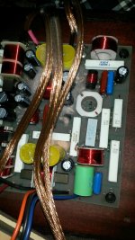
Edit to add pic of crossover
So looks like the Seas option will keep things simple until I can learn more of the answers I need to optimize later. That could lead to moving to the SBA design and a new HF crossover should I choose to keep these speakers and tinker more as I learn more.
Been reading about recapping crossovers and that alone can get a guy way off on a tangent. Can anyone give me a basic recommendation? The one common theme is that at 25 years, yes I should probably do something. So to keep things simple I was wondering:
1. Should I replace all caps in all 3 sections?
I was thinking of leaving the woofer section alone and focusing on mids and tweets for greatest effect
2. Should I do all caps in a particular section or is it more important to do the series caps and leave the shunt caps alone. Or is it vica versa. Or is it more about type of cap that one focuses on.
3. To keep life simple I would replace like for like unless someone can suggest that for a typical function, say a series cap, that technology has changed and I should change type x for type y when possible.
I thought it was as simple as measuring capacitance as a go/no go decision maker on what to change but that does not seem valid so looking for general thoughts or where I need to learn and understand more without getting way off course.
I hear you about business Doug. If it goes on much longer people will need to decide if they are free to earn a living, associate, travel or simply have no rights.
Also, I didn't realize things have progressed to where there is free software and a $100 mic is all that is needed to do measurements in my own home. To have that 25 years ago instead of spending $60 on just a sound level meter.
Edit to add pic of crossover
Attachments
Last edited:
Hi Ken,
I would recommend against diving down the recapping hole ( certainly at this point in time ) specifically for the midrange and hi-frequency parts of that crossover.
You might want to start by testing the capacitance ( & ESR ) values of all those electrolytics that I see in the bass portion of the network.
- Replace with non-polarized of the same value if you find any that are out of spec.
The HF portion of your crossover is populated with a variety of different industrial poly types ( of which, I happen to have a few examples here ).
One example, that light cap ( lower right corner ) is no doubt a 4uF cap made by Ero.
- It's poly film type is MKC ( polycarbonate ) and that actually sounds quite nice with metal diaphragms.
- I would keep it in circuit.
🙂
- Home
- Loudspeakers
- Multi-Way
- Energy Veritas 1.8 tweeters quit