Have you written one for Heil's magnetostatic AMT, Michael? It would be great to get a feel for the membrane forces for that case.
A good idea, David!
But what I see as a problem is that for magnatostatic AMT we do not have reliable data for
- mass
- B*L
- pleat dimensioning
Manufacturers (Mundorf, Beyma...) only provide veeery sparse data.
How should we compare, any suggestions?
Michael
AMT sheet
I was thinking it would just be written to derive the Lorenz force and the foil temperature rise from the essential parameters of the magnet's magnetization or magnetic moment and physical dimensions, magnetic gap width, the current, the foil thickness, dimensions, density, and conductivity, and the pleat depth and gap. I think it seems okay for this purpose to simplify by assuming the static field is at a perfect right angle to the current flow, and also to ignore the dynamics and assume DC current flow. Might be worth searching to see if anyone published such a thing already, though, which I have not done. Seems like it would be a great 2nd semester physics project for a smart kid.
But what I see as a problem is . . .
I was thinking it would just be written to derive the Lorenz force and the foil temperature rise from the essential parameters of the magnet's magnetization or magnetic moment and physical dimensions, magnetic gap width, the current, the foil thickness, dimensions, density, and conductivity, and the pleat depth and gap. I think it seems okay for this purpose to simplify by assuming the static field is at a perfect right angle to the current flow, and also to ignore the dynamics and assume DC current flow. Might be worth searching to see if anyone published such a thing already, though, which I have not done. Seems like it would be a great 2nd semester physics project for a smart kid.
Hi All, I think our understanding of the issues involved in AMT's in general, and the ES version in particular, is advancing thanks to your input and stimulus.
When we read the Heil patent he has no problem with f figures of 10, yet in the working version this is halved to around 5, Why?
Could it be that the pleats cannot be creased sharply enough to cram them into the space available?
Could it be that the creases are rounded as if wrapping around posts that do not exist creating the "dead air" situation?
Are there noise generation issues due to turbulence or the pleats contacting one another?
Maybe the motor force is inadequate?
For any, or all, of these reasons retreating to a lower f makes sense. It also makes sense in the ES version, but not without problems. Chief among them is the way we end up with an excursion potential that we cannot use due to membrane tension. By varying the angles of zig zag pleats we can change the f number. I was about to write "average f number" in the belief that it was high in the bottom of the pleat opening and low at the top. This would be true when we consider the pleat depth as being fixed, and note the way the width varies as we move our width measuring ruler up and down the depth dimension.
Another way to look at it is as a sequence of air layers being progressively less compressed as they approach the open air, but with the same f number as boundaries. Not certain what it all means!
For anyone who has doodled with serpentine shapes, as in AMT's, it becomes obvious that at each end we have a "half strength" pleat. The final opening is bounded by a pleat that moves and one that does not move, so reducing the spacing seems in order. The Heil woofer, called Transar, was an example of a half strength AMT, and an example of zig zag construction; actually sawtooth. Endlessly fascinating!
Keith
f evaluation
I forgot to mention that the effective area of the planar ESL can be varied by simply taping over areas of its surface. Between changing the area of the ESL and the area of the solid surface, the effects of the f number and pleat depth can be investigated quite easily. Driving a planar ESL in the first place will also validate the signals and bias.
I forgot to mention that the effective area of the planar ESL can be varied by simply taping over areas of its surface. Between changing the area of the ESL and the area of the solid surface, the effects of the f number and pleat depth can be investigated quite easily. Driving a planar ESL in the first place will also validate the signals and bias.
A belated insight
When you think about it the standard EM AMT designer is changing his f number by "concertinaring" the pleats. It is just that he has to operate within the constraints of a frame; so to reduce f he has to remove the membrane and snip off a few pleats and reinstal it. Thus any distiction between zig zag and parallel pleats becomes rather blurred. It gets down to a question of how sharp the folds are. Of course the ES case calls for parallel pleats or an appropriately shaped stator or other mechanism to achieve an even force over the pleat area when they depart from parallel.
Keith
In other words
You might say that triangular gaps reduce the acoustical impedance while also reducing the vibrating area relative to parallel pleated gaps. For ED AMT's, there is probably a well characterized relationship published somewhere between the pleat geometry and the spectrum and SPL per unit area. Also, in designs where the magnetic field runs fore and aft while the current runs side-to-side, the force will be reduced by a factor of the cosine of the angle of each pleat away from parallel, e.g., a 90 degree included angle will produce .707 times the force, equivalent to halving the area.
When you think about it the standard EM AMT designer is changing his f number by "concertinaring" the pleats. It is just that he has to operate within the constraints of a frame; so to reduce f he has to remove the membrane and snip off a few pleats and reinstal it. Thus any distiction between zig zag and parallel pleats becomes rather blurred. It gets down to a question of how sharp the folds are. Of course the ES case calls for parallel pleats or an appropriately shaped stator or other mechanism to achieve an even force over the pleat area when they depart from parallel.
Keith
You might say that triangular gaps reduce the acoustical impedance while also reducing the vibrating area relative to parallel pleated gaps. For ED AMT's, there is probably a well characterized relationship published somewhere between the pleat geometry and the spectrum and SPL per unit area. Also, in designs where the magnetic field runs fore and aft while the current runs side-to-side, the force will be reduced by a factor of the cosine of the angle of each pleat away from parallel, e.g., a 90 degree included angle will produce .707 times the force, equivalent to halving the area.
AMT is a clever name used to obscure the real motivation behind the design.
motion transformer !
accelerating air !
WOW !
not really ...
pleating is BAD. they HAD to do it in order to organize the field around the ribbon element in an efficient way.
you see for good field u want it not to have to jump across a wide gap. now ribbon is large in two dimensions but zero in third. they needed a way to orient the field along the third dimension in which ribbon is flat - and they did just that with AMT.
then they had to think of a way to sell it - so they came up with the clever marketing name of "air motion transformer"
in ESL you're already having the field in the right place. it doesn't need any fixing.
i analyzed cons and pros of various geometries such as ESL and AMT before writing this:
http://www.diyaudio.com/forums/planars-exotics/151474-plur.html
the design challenge is to match the shape of the field to the shape of the diaphragm. ribbon speakers don't do this which is why AMT is a solution to that problem. my PLUR technology is another ( more elite ) solution to that very same problem.
thing is as i said ESL doesn't have this problem to begin with so you're solving a problem that doesn't exist with an electrostatic AMT ...
OK then, heres a weird variant....
Supposin you let the each pleat touch both neighbors? Not short, just touch...
They would all need one dielectric surface oriented to insulate those meetings.
So anyways, you now got two caps fighting for posession of a surface area.
The pleat peels away from one cap and onto the other, until charge per area
are equalized. But then there is this peel effectively sliding back and forth...
Does this direct contact method avoid the non-linearity of field inbetween???
Could it be done with less Voltage since the distances involved are less???
Would Stiction or Van der Waals mess this up, or are those in balance???
Last edited:
Does the reduced distance now make the motor strong enough for the purpose???
Does this solve the problem of high frequency rolloff with increasing pleat depth???
I mean, even if the pleat is some absurd 30 inches deep, you got only a small part
of the pleat peeling from one surface to the other at any time. Or have I somehow
misunderstood the implications???
Does this solve the problem of high frequency rolloff with increasing pleat depth???
I mean, even if the pleat is some absurd 30 inches deep, you got only a small part
of the pleat peeling from one surface to the other at any time. Or have I somehow
misunderstood the implications???
Very good thinking Kenpeter. If I understand you correctly you are alluding to something I had thought of in a half baked way. A drawing would be very usefull here. For purposes of explanation the "pleat" could look like a capital H. Maybe the vertical parts are rigid stators with a very floppy membrane running diagonally across the opening. When the horizontal element of the H is in the centre this position is created by the lower part of the membrane "sticking" to one stator and the upper part to the other. Thus we are exploiting something that Electrostatics is good at--generating force with small spacings. We also consign membrane tension to the rubbish bin.
This idea needs a lot of thinking about as the motion is quite unlike that encountered in 99% of transducers. David mentioned adverse effects of zig zag pleats in an EM AMT. I could be wrong, but tend to view the pleats as having a rigid part (The conductive foil) and a floppy part (The folds). Perhaps, under drive, the folds alternately "balloon" out and pull taught to preserve parallel pleat motion.
Keith PS Borat, I have to disagree with your aversion to pleats. Ignoring motor means, pleating confers advantages in getting an improved impedance match to the air and can result in an acoustically smaller transducer with directivity benefits. Your idea would work well in an AMT!
Last edited:
kenpeter's idea
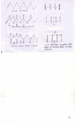
In the drawing I am attempting to explain kenpeter's idea. All aspects of practical realisation have been neglected. When we consider the crackling noises associated with unwinding sticky tape from a spool we may have a serious problem. I think kenpeter was envisioning a hand over of the sticking area from the bottom of the pleats to the top. This would defeat AMT motion and leave you with something like depicted on the right.
Keith
Attachments
Kenpeter's traveling meniscus motor
Wow, Keith, very astute. I did not understand, until I saw your sketch.
What an interesting idea, kenpeter. Surely not one that lends itself to easy realization, but puts forth a quite intriguing motor mechanism. On the plus side, in its ideal form, it would apply the absolute maximum possible electrostatic force. I won't begin to list the challenges.
About the AMT impedance match, I feel I am repeating myself ad nauseam, but the membrane in an AMT experiences a higher impedance air load than in a planar. I believe this is disadvantageous when driving electrostatically, where the extra loading is likely to more than offset the increase in driven area. ESL's are already as well matched as possible to the air load.
In the drawing I am attempting to explain kenpeter's idea.
Wow, Keith, very astute. I did not understand, until I saw your sketch.
What an interesting idea, kenpeter. Surely not one that lends itself to easy realization, but puts forth a quite intriguing motor mechanism. On the plus side, in its ideal form, it would apply the absolute maximum possible electrostatic force. I won't begin to list the challenges.
About the AMT impedance match, I feel I am repeating myself ad nauseam, but the membrane in an AMT experiences a higher impedance air load than in a planar. I believe this is disadvantageous when driving electrostatically, where the extra loading is likely to more than offset the increase in driven area. ESL's are already as well matched as possible to the air load.
Don't know that it could actually kink over hard 90 that way?
Was thinkin something halfway between pic on the left and
right. Or perhaps an S shape rolling down the middle of this
crazy audio railgun...
Course, any slack (obviously some is necessary) is gonna
crack like a whip if this rolling wave hits XMAX either end.
Picture crew of the Argo shouting in unison "Prepare to fire
the wave motion tweeter!"
Last edited:
Digital Leyden Jar Transducer
Okay, what if the goal were to normally drive cells to their limits, but use an array of cells, all of different depths? Each would take a different amount of time to reach its limit. When there is a very high frequency input, for instance, a majority of the shallow cells would bottom out, but not the deeper ones. At lower frequencies, the deeper cells would "take over" when the shallower ones have bottomed out. The aggregate mechanical response might produce sound.
Further, if the shallow cells were arranged at the center of the array, and cells became progressively deeper with increasing radius from the center (circular transducer) or distance from one edge or the center-line (line transducer) , this might create a holy grail variable aperture that would provide uniform dispersion at all frequencies.
Of course, I think the physics of the basic motor would preclude the development of any real force, because even if unwanted membrane-to-membrane charge transfer and induction problems could be solved, and materiel fatigue were not a problem, and the thing could be fabricated, and the air load were not an issue, still the area where the force would be applied is only in the near vicinity of the line where the membranes meet, but hey, I still love the idea.
A first pass apparatus might be variant on the Leyden jar, with a strip of polarized membrane suspended between two stators, attached at the bottom of one stator and the top of the other. If the part that crosses between the two strips can be made to climb up and down the stators, that would at least be a cool science demo.
Don't know that it could actually kink over hard 90 that way?
Was thinkin something halfway between pic on the left and
right. Or perhaps an S shape rolling down the middle of this
crazy audio railgun...
Course, any slack (obviously some is necessary) is gonna
crack like a whip if this rolling wave hits XMAX either end.
Picture crew of the Argo shouting in unison "Prepare to fire
the wave motion tweeter!"
Okay, what if the goal were to normally drive cells to their limits, but use an array of cells, all of different depths? Each would take a different amount of time to reach its limit. When there is a very high frequency input, for instance, a majority of the shallow cells would bottom out, but not the deeper ones. At lower frequencies, the deeper cells would "take over" when the shallower ones have bottomed out. The aggregate mechanical response might produce sound.
Further, if the shallow cells were arranged at the center of the array, and cells became progressively deeper with increasing radius from the center (circular transducer) or distance from one edge or the center-line (line transducer) , this might create a holy grail variable aperture that would provide uniform dispersion at all frequencies.
Of course, I think the physics of the basic motor would preclude the development of any real force, because even if unwanted membrane-to-membrane charge transfer and induction problems could be solved, and materiel fatigue were not a problem, and the thing could be fabricated, and the air load were not an issue, still the area where the force would be applied is only in the near vicinity of the line where the membranes meet, but hey, I still love the idea.
A first pass apparatus might be variant on the Leyden jar, with a strip of polarized membrane suspended between two stators, attached at the bottom of one stator and the top of the other. If the part that crosses between the two strips can be made to climb up and down the stators, that would at least be a cool science demo.
ESL's are already as well matched as possible to the air load.
Hardly ! And to repeat myself - learn the basics !
- are you sure you are *the* Janszen ?
Michael
Last edited:
Posted by DavidJanszen: "ESL's are already as well matched as possible to the air load."
Hardly ! - are you sure you are *the* Janszen ?
Michael
OK, so please illuminate us concerning the nature of the impedance mismatch between the ESL diaphragm and its air load.
You makin it too complicated. But if you are determined to go there...
I don't see how havin middle bottom out early prevents the deeper
outer portions from transducing treble. Dispersion worse, not better?
Now, you could run an array of cells with a hemispherical DC offset.
that would make the wavefront appear to come from a dome... Or
have cells that simply stick out further in the middle? But that might
be tougher to manufacture than fakin a dome shape with DC...
I'm really more concerned how to make XMAX a less traumatic event?
How does one absorb the energy of the whiplash without shredding
the ends of the ribbon in the process? Or is transfer of energy to air
good enough all by itself to provide that damping?
Might be a moot point? I think XMAX here is arbitrary. We can make
stators and ribbon as lengthy as air friction losses will allow. Its not
frequency limited by depth in the manner of an AMT, where you are
fighting to sum phases from distributed depths within the same pleat.
Last edited:
Basics
Son of.
Of course, I would suggest a similar directive regarding the basics to you.
I will review the validity of your contention that the air impedance is inconsequential to an ESL, and report back. For now, as I have already said, I believe that compounding the air load, such as with pleats, will decrease the amplitude of membrane motion for a given amount of force, not that this is the only attenuation mechanism at work in an AMT.
In the meantime, please don't let this stop you from backing up your assersion with an expplanation of some sort.
Hardly ! And to repeat myself - learn the basics !
- are you sure you are *the* Janszen ?
Michael
Son of.
Of course, I would suggest a similar directive regarding the basics to you.
I will review the validity of your contention that the air impedance is inconsequential to an ESL, and report back. For now, as I have already said, I believe that compounding the air load, such as with pleats, will decrease the amplitude of membrane motion for a given amount of force, not that this is the only attenuation mechanism at work in an AMT.
In the meantime, please don't let this stop you from backing up your assersion with an expplanation of some sort.
Last edited:
You makin it too complicated.
You think so? 🙂
Anyway, I think it's fun to think about damage from an ES rail gun whipping to its limits, but as a real concern, now might be too soon. The initial challenge with any new transduction or motor scheme is getting it to move at all. I think if you can get the Leyden jar thing or something like it to work, though, you might be on to something.
- Home
- Loudspeakers
- Planars & Exotics
- Electrostatic AMT?