Son of.
Yeah, I know.
But of the same format too?
For now, as I have already said, I believe that compounding the air load, such as with pleats, will decrease the amplitude of membrane motion for a given amount of force, ...
Might be we are in a discussion about half full versus half empty – but I doubt.
I agree that there will be less excursion for a given initial radiating diaphragm area when folding this very ESL – so what?
Same effect if you put a horn in front of any driver - - - - - what does this tell us ?
You make the same mistake you did some postings ago (about balancing of break down voltage versus force obtainable when varying gaps) where you "forgot" to look at the second side of the equation.
Another paramount mistake of yours is the wild guess that ESAMT would only work respectively have its strength at the top end if any – way off !
Therefor my "back to the drawing board", David...
...not that this is the only attenuation mechanism at work in an AMT.
As said before – I don't have the feeling you know about AMT .
Always sounds like you *have* to defend and put forward ESL and down talk anything else – bad salesman habit in the context of a DIY forum and not at all helpful ( IMO ) when it comes to discussion of something not been seen before like Keith's ESAMT invention.
Have you ever seen SPL or distortion plots of a new generation AMT or gave it a listen?
If so, you should be aware that both, sensitivity and distortion figures are nothing to complain about.
So either you know *nothing* about AMT or you are trying to tell us – what ???
Michael
Last edited:
Keith
Guess again the basics got lost - no way to make something useful with no well defined 0 frequency (rest) position of the diaphragm - meaning there *must* be sort of resonant frequency too - cant see the therefor *necessary* spring here ???
Otherwise only a servo system is possible - meaning you have to sense and feed back the excursion and mimic a oscillating system synthetically - for each and every pleat separately of course
Michael
Yup, like slammin into XMAX at some unknown endpoint, its an unresolved unknown.
And the ribbon touching both stators (through dielectric) is at no specific Voltage.
You can't read back a position, you just pump in or suck out a number of coulombs
you want it to move... But move from where?
My suggestions involving Voltage offset are equally ridiculous until said Voltage has
some sort of spring to center and give something for those Volts to work against.
I'm open to simple suggestions not involving servos.
If the electrical width of each stator was of lesser at one end than the other???
Each tapered the opposite way... Would this tend to center the ripple in the middle
where the averaged capacitance is highest?
Last edited:
I agree that there will be less excursion for a given initial radiating diaphragm area when folding this very ESL – so what?
Same effect if you put a horn in front of any driver - - - - - what does this tell us ?
An AMT is not like a horn. A horn takes a high impedance transducer and matches it to the much lower impedance of the open air. Pleating a diaphragm takes a low impedance transducer and presents it with an higher impedance load. Your assertion to the contrary is puzzling.
Another paramount mistake of yours is the wild guess that ESAMT would only work respectively have its strength at the top end if any – way off !
I have no idea what you are referring to. I have never generalized, but been careful to relate statements about frequency cutoff to membrane span distances, tension, etc. Anything else must have been a misreading resulting from your inexplicable desire to cast me in a negative light.
.As said before – I don't have the feeling you know about AMT
I am sorry, but this statement is nonsensical in English. Please try again.
Always sounds like you *have* to defend and put forward ESL and down talk anything else – bad salesman habit in the context of a DIY forum and not at all helpful ( IMO ) when it comes to discussion of something not been seen before like Keith's ESAMT invention.
I have not denigrated AMT's or defended ESL's. I have only stated what I think are the facts in relation to Keith's idea, which is what this thread is about. To do otherwise would be wrong, as you point out. Please stop with the personal accusations, try to understand what I really wrote, and please also do not confuse me with my company. I keep an open mind.
Have you ever seen SPL or distortion plots of a new generation AMT or gave it a listen?
If so, you should be aware that both, sensitivity and distortion figures are nothing to complain about.
Who is complaining? You seem to be defending AMT's, when there has been nothing bad said about them.
So either you know *nothing* about AMT or you are trying to tell us – what ???
I am trying to say that although ED AMT's work, I think ES AMT's will not. I have tried to say why I think this. That is all. You seem to be reading more into it than that. Please please please stop these digressions.
A horn takes a high impedance transducer and matches it to the much lower impedance of the open air. Pleating a diaphragm takes a low impedance transducer and presents it with an higher impedance load.
Wow...
seems I never stop learning...
Michael
Last edited:
As said before – I don't have the feeling you know about AMT
I get it, now. You think I do not know about AMT's.
How is that ED- AMT spreadsheet coming along?
I get it, now. You think I do not know about AMT's.
Persuade the opposite - welcome at anytime...
I was thinking it would just be written to derive the Lorenz force and the foil temperature rise from the essential parameters of the magnet's magnetization or magnetic moment and physical dimensions, magnetic gap width, the current, the foil thickness, dimensions, density, and conductivity, and the pleat depth and gap. I think it seems okay for this purpose to simplify by assuming the static field is at a perfect right angle to the current flow, and also to ignore the dynamics and assume DC current flow. Might be worth searching to see if anyone published such a thing already, though, which I have not done. Seems like it would be a great 2nd semester physics project for a smart kid.
How is that ED- AMT spreadsheet coming along?
...eloquent like any Troll's name dropping - to be honest
😉
Michael
Last edited:
Still hoping for an explanation of how one might improve on the impedance match between an ESL diaphragm and its air load...
Few
Few
I came across the following patent text while exploring acoustic impedance. The second half refers to the fact that the impedance of an air load can become too large when the air is overly confined. Seems pertinent---especially given the "All these theoretical results have been experimentally confirmed" statement.
Given the large forces typical of piezoelectric devices such as the PVDF example above, and the extremely low mass typical of current ESL diaphragms, I think the risk of the ES-AMT approach mucking up an inherently excellent diaphragm/load impedance match is high. I say this with regret, since I was quite excited about pursuing this approach myself, at one time. Nonetheless, if the impedance match truly is a problem, it seems like a deal-breaker.
Few
This paper investigates acoustic wave radiation from cylindrical polyvinylidene fluoride (PVDF) film mounted inside a concentric wall with a small air gap. In such a structure, propagation is allowed only in the gap between the film and the wall surface, and the wave propagates in the axial direction of the cylinder. The radiation impedance of the cylindrical transducer inside the concentric wall has been calculated using a one-dimensional propagation model. After calculating the mechanical impedance of the cylindrical PVDF film, the generated acoustic wave has been calculated as a function of frequency with various air gaps between the PVDF film and the wall. It has been found that the excited acoustic wave becomes stronger for a narrower air gap and shows a maximum at a specific air gap. This phenomenon has been explained as the match between the transducer impedance and the radiation impedance of the air gap. When the gap is too small, the radiation impedance exceeds the transducer's mechanical impedance, the acoustic wave radiation decreases with the decreasing gap, and the resonance frequency increases due to loading by the imaginary part of the excessive radiation impedance. All these theoretical results have been experimentally confirmed.
Last edited:
first of all there is no need for any impedance transformation with electrostats as you can simply vary the material thickness to get impedance you want.
secondly you could always just horn load the driver without any pleating. there is just no point in doing it with anything but dynamic drivers which suffer from obesity.
secondly you could always just horn load the driver without any pleating. there is just no point in doing it with anything but dynamic drivers which suffer from obesity.
Still hoping for an explanation of how one might improve on the impedance match between an ESL diaphragm and its air load...
Few
Simply - there *is* nothing to match...
Seen from the motor you only have load - be it the mass of the "membrane (load)" or the "mass" of air load.
Hence it's kinda nonsense to claim "low/high impedance transducer"....
#########
Obviously shifting the ratio of membrane mass versus frequency dependent radiating impedance in favour towards zero membrane mass (= which has the same effect as increasing radiating impedance for a given diaphragm mass towards infinity) increases efficiency.
*If* the ratio of parasitic mass (membrane) to radiation impedance is already - say 10 times - in favour to air load - there is not much room left for improvement (90% versus 100% to be precise).
In the lower department obviously this very ratio isn't any good, thus becoming the Achilles heel of all ELS' (not only - mind you)
So - any improvement here will be a biiiig step forward - and as most are aware of – to attach horns that still load in the bass isn't any WAV friendly.
IMO above considerations should form the guide line for any new ESAMT prototyping – and as far as I've read, Keith has already understood the direction I'm pointing at.
###########
Pretty sure David will come along in a U turn to tell us he " even know better from both experience and arithmetic, but had a brain fart"
http://www.diyaudio.com/forums/planars-exotics/153220-electrostatic-amt-2.html#post1969784
😉
Michael
Last edited:
Simply - there *is* nothing to match...Seen from the motor you only have load - be it the mass of the "membrane (load)" or the "mass" of air load. Hence it's kinda nonsense to claim "low/high impedance transducer"....
The fact that the motor in a dynamic driver feels a net load from the combination of the diaphragm's mass and the air load doesn't eliminate the importance of coupling the diaphragm's motion to the surrounding air. Why do we need a diaphragm in the first place? Because the motor can't couple effectively to the surrounding air without it. To make sound a loudspeaker must couple the energy associated with its own motion to motion in the surrounding air. Its ability to do that depends on the impedance match between the two.
Another way to think about it is by imagining operating a loudspeaker in reverse: sound waves impinge on the diaphragm and we consider how well the sound energy is converted into motion of the diaphragm. If the air/diaphragm impedance match is poor (as is typically the case with dynamic woofers, for example) then much of the sound energy is reflected with little induced diaphragm motion. If the impedance match is good (as in the case of an ESL diaphragm) then much of the sound energy can be converted to diaphragm motion and there is less reflection. Notice that all this is equally true even if there's no motor on the diaphragm, which implies there's more to this than coupling the motor to a total air/diaphragm load.
Few
Mmhh, no – don't think so, Few.
The two cases, mic versus speaker are fundamentally different in this respect.
I would agree though to your arguments *if* you take the challenge to construct a mic with *vacuum* behind the membrane.
In this – rather academic – case you are spot on to match the diaphragm's impedance to that of the air so that the waves arriving do not get reflected .
In case of a speaker, diaphragm mass is *always* parasitic (as is the spring in the compliance dominated region below F-res) – all that counts is to make the ratio of "air load" veeeeery large with respect to "membrane mass" – something that does not need any "matching" – at least in German we would not associate the term "matching" (balancing) to a sheer optimisation towards infinity.
So maybe its semantic?
Michael
Last edited:
Few, thanks for that, I was about to mention similar things in a post that I have been working on. I wish I could answer some of the questions being asked here but am constrained by a kindergarten level of acoustics understanding. The bottom line for transducer efficiency is the ammount of acoustic power that can be generated for the electrical power input. In ED transducers such as cones and domes etc around 99% of the input power is used to accelerate the moving mass instead of moving air. With ESL's the power demand is more wattless, meaning the load is reactive. Here the amplifier has to supply increasing current at higher frequencies to charge the capacitances of the ESL.
Somewhat akin to transmission lines air has a characteristic impedance given by p/u. p being pressure and u particle velocity. In a discussion comparing the impedance conditions in the presence of boundaries with that encountered by a freely propagating wave we have to conclude that the impedance is lower away from boundaries. Depending on the units of measurement in use it is 407 mks rayls (acoustic ohms). p in the numerator stays low as there are no containment boundaries to cause a build up and u is high as there are no boundaries to arrest particle motion. Perhaps somewhat counterintuitively for an electrical theory person, when a propagating wave meets a boundary we do not have a short circuit and a low impedance, but the opposite. The pressure increases and the partical velocity tends to zero, thus we have a higher impedance.
As in electrical theory, power is not due to E or I alone, but is the product of the two. Also, only the real part of a complex impedance takes power from the generator, the wattless (reactive) part being returned to the generator. Impedance matching is a two sided affair where we can examine the electrical load a transducer presents to the amplifier or the impedance the transducer is presenting to the air. Sadly, with efficiencies of around 1% the radiation impedance gets totally masked by transducer mechanical impedances.
Under "radiation impedances" Beranek examines four types of radiator.
A pulsating shere
A plane circular piston in an infinite baffle
A plane circular piston in the end of a long tube
A plane circular piston without a baffle
The real and imaginary parts of the radiation impedance are plotted in magnitude against ka (acoustic size). If there is a textbook analysis of the pleated membrane I am sure we would all be interested. Perhaps noting the shapes of a quadratic residue diffusor tells us that there is something quite different about pleated shapes compared to flat or curved ones. That difference is likely to be in the acoustic impedance that they present to incident waves.
Armed with these kindergarten understandings does at least allow us to question the assertion that a memrane powered by X means has a "perfect" match to the air. This seems to depart from the subject which is about having a radiator where the electrical load has a maximised real part and a minimised imaginary part over the frequency range of interest. The Ronald Wagner book has a chapter by Walker which is quite informative re radiation resistance. In ESL's the dominant loads are the reactances due to stiffness and mass. In the region where these transition from spring to mass we see a real part to the impedance. Walker says "The impedance (Z) may include dissipative terms in the form of absorption and/or acoustic radiation resistance". Let's have three cheers for the dissipative terms, as they are pretty hard to find in most transducers!
Keith
Last edited:
. . . am constrained by a kindergarten level of acoustics understanding.
You are way beyond that, Keith. 🙂 Very nice summary of a big subject. Anyone else who is interested in acoustics would also enjoy deep insights from reading Bernanek (or Olson), regardless of your background. BTW, in terms of the effect on the returned wave, there is correspondence between acoustic waves striking a solid boundary and EM waves striking a conductive surface.
FWIW, here is an AMT patent from this decade, where the authors based their invention on 1) the benefits of using a horn to match an AMT's relatively high acoustical impedance to the open air, and 2) the benefits of finding ways of providing greater uniformity in the field and in the acoustic coupling. They cleverly designed a magnetic and support structure so that it integrates uniform and optimal load matching and simultaneously optimizes field uniformity.
They assigned it to Cerwin-Vega (may have been employees of the company), who obviously have a strong interest in efficient transducers. Have not seen a product, yet, although they had apparently a coaxial design on the market long before. Unfortunately, their figures do not include data from their research, but maybe they published a paper.
Attachments
ES AMT US patent 5479061
Have you seen US5479061, Keith? Although this invention is meant for fabrication using microelectronics methods, and the scale must be pretty small, it does appear to teach a stator-less dielectric membrane ES AMT. Unfortunately, the pdf is much too big to upload, and it zips to an even bigger file for some reason.
Best route IMO is Patent US5479061
Attached the cover page extracted from the original pdf.
Way off topic, but just learned that Gene Czerwinski, first author of the integrated horn AMT patent attached to the previous posting, was the founder of Cerwin-Vega, so I know finally where the company name came from.
Attachments
Last edited:
David,thanks for the patent links. Czerwinski has written a few AES papers but I did not realise they were into pleated diaphragms. There seems to have been a level of pent up interest at the time of the Heil patent expiry. Yes I had come across the micromachined transducer by searching US patents. Found it pretty hard to take in, but if you read between the lines the references to ES powering means and some kind of a similarity to a pleated structure becomes apparent. If patents are supposed to have a teaching function not certain what this one teaches. Maybe how to use a lot of words without giving too much away.
Keith
Keith
. . . what this one teaches. Maybe how to use a lot of words without giving too much away.
🙂
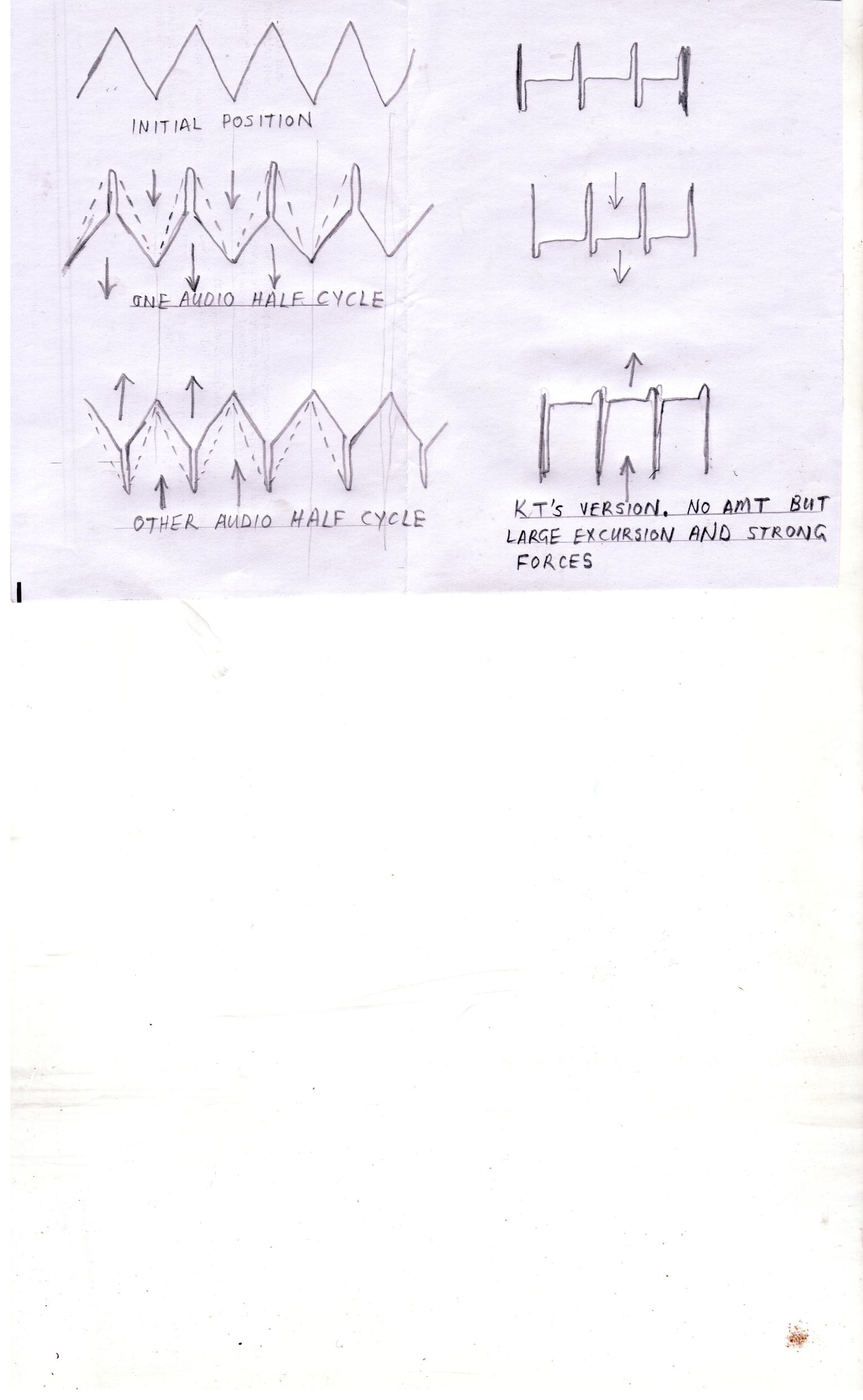
OK, I've had a bit of time to think on servoless centering
for the half baked wave motion version.... My suggestion
about tapering the electrical width of the stators maybe
varies the impedance and/or motor strength, but I don't
see how it looks or act much like a mechanical spring.
Got a new half baked idea: Supposin we were to curve both
stator surfaces slightly? So's gap inbetween is shortest near
the middle of the device. Now the length of a crossing peel
varies with the displacement, and subtracts from the overall
capacitance stuck to the stators, causing both physical and
electrical tensions to rise. Stator capacitance becoming our
spring we were needing?
- Home
- Loudspeakers
- Planars & Exotics
- Electrostatic AMT?