Perhaps the arcing over 2.8mm is not unexpected.
I see. No, not unexpected.
David, the present construction is . . .
Thanks. Got it. Your pleat depth is more than enough to keep limited span from causing low compliance to be an issue that prevents membrane motion. Your gap is very wide, and has to be to have any chance of radiating sound, yet narrow enough to allow plenty of force at the voltages you have available. Once everything is in order, you will get sound, unless I am right about the loading situation.
The power amp seemed to be experiencing some dificulties . . .
If you do not have a bridge or other means of measuring the capacitance across the signal pairs, you can calculate it. Once that is done, you multiply this capacitance by the square of the step-up ratio to see what capacitance appears at the amplifier's output.
Some amplifiers will become unstable with a capacitive load above a certain value, because their phase margin may have been set based on having a mostly inductive/resistive load from dynamic speakers, and regardless, capacitive loads represent a low impedance at high frequencies. I believe that your device has a quite low capacitance, maybe just as a wild guess 80 pF or so, but in practice, a real device will be larger and have more.
Let's say the device capacitance is 250 pF and the step up ratio is 1:100. 250e-12 * 100 * 100 = 2.5e-6, or 2.5 uF. This must be added to the transformer's parasitic capacitance, with which it is in parallel, and which can be quite high at high ratios, say, another 1 uF for that ratio. 4 uF at 20 kHz is about 2 Ohms. Leakage inductance resonating with the capacitance can be another problem, both for amplifiers and transducers, even when it is out of band.
David J, I can see that you are quite an electronics person. I am retired but solving electronic problems was quite a large part of my working life. Had a read of the Heil patent US3636278 for the first time in quite a while. As patent documents go it is reasonably digestable. No where does he suggest that air mass loading is going to be a significant problem for the EM version.
I know my prototype is probably not running on all cylinders but I tried (with some difficulty) to explore what is happening above resonance with my cheap SPL meter about 2 inches from the membrane. I actually own some very good condenser mics I use for recording. The news is good in that it appears to go beyond 20kHz. This seems to equate with Heil's statement that "A depth (pleat) of 10-15 mm will give perfect efficiency up to 10-15 kHz". In the patent Heil often mentions pleat depth to width ratios (his f factor) of 10 but I understand the models appearing in the market place are more like 5.
What I am thinking at the moment is that I need to try and lower the resonance frequency considerably. Maybe sealing the ends will help but it will impede debugging work on the present membrane. Heil favoured ordinary polythene film as a membrane material and I am wondering if this would give more compliance to the ES version. Leakage and voltage breakdown seem a viscious circle. I am getting audio and bias arcing with the present pleat spacing and if I go for smaller spacing I need less drive voltage but then the arcover distances will be smaller. The project calls for very accurate processes such as etching and a lot of attention to cleanliness: difficult to achieve in a hand built prototype.
Finally got around to earthing the transformer CT and found the bias stopped arcing over. It later started arcing again which was probably more to do with the weather, today being warmer and dryer than yesterday.
Keith PS, I have a 1.7 ohm resistor in series with the transformer primary to make the amp a bit more abuse proof. I was surprised at the ammount of signal being dropped across it.
Last edited:
No where does [Heil] suggest that air mass loading is going to be a significant problem for the EM version.
My contention is that this is because there is lots of force available. Still, I am sincerely hoping I am wrong that so much less is available from an ESL. I would do the math or a simulation for both cases, but kind of busy. This would be a great exercise for someone . . .
What I am thinking at the moment is that I need to try and lower the resonance frequency considerably.
More compliance (by means of floppier material or less tension) will only reduce the lower cutoff, and it seems you have found it to be already well within the audio band. If you can't get sound out at 10 kHz, then, reducing the cutoff will not help.
When you plot the response, do you see a roll-off, i.e., a high pass response? If not, then the cutoff may be above the audio band, but in that case, it would be hard to tell if more compliance would help, or if the loading situation is suppressing membrane motion throughout the band.
I am getting audio and bias arcing with the present pleat spacing
If all connections are okay, this means you are applying as much force as possible, given the electrical breakdown limitations. It is breakdown that limits voltage, thus force.
Magnetic fields have the advantage of not arcing, but wouldn't it be interesting if they did arc? Maybe in another universe.
Things are a bit in the doldrums as to which way to go next. Tried David's needle method of sensing charge on the biased pleats and no corona discharge seen or heard. Presumably, we are expecting a hissing sound, a faint glow and the smell of ozone? Find it hard to think in a pure ES theory domain. Thus I am thinking that maybe the high resistivity of the coating is some impediment to a discharge ocurring; when I should be viewing the biased pleats as reservoirs of excess electrons or protons "topped up" by the bias supplies and the resistivity counts for nothing except to distribute the charge more evenly.
Found that the conductive coating can be removed with the aid of methylated spirits and moderate scrubbing, but there would be little solvent action. Tried transfering some liquid coating into the bottom of the pleats where contact with the bias posts is made. It did not change anything and some ended up where not wanted. When the membrane was unlaced the biased pleats were adhering to the posts, so contact should have been good.
Using a single bias supply to get +and - supplies may not be a good idea, or on the other hand, it could be a measurement problem. If I connect my none too high impedance multimeter to 0 volts and measure the voltage in 500 V increments a non linearity becomes apparent. The further you get away from the transformer the poorer the regulation becomes. I thought there may be a leaky diode or capacitor, but nothing obvious. Cleaned the board also. One idea I had was to break the supply into two by removing a pair of diodes in the middle of the voltage multiplier and wiring the transformer secondary to what was the highest voltage tap. Could involve some track cutting which may not be a good idea for something that may not work.
Keith
Initial debugging seems almost done
Indeed.
One more thing to think about if you eventually get sound out of this is that you are up against Coulomb's law and breakdown combined. ES force goes as the inverse square of gap but the breakdown goes as the direct. In other words, for each doubling of the gap, there is 1/4 the maximum force avaialble.
Most of the coronal light is UV, and if your coating is transparent, you could try putting a piece of white paper behind the film, which will glow bluish from the UV. Only in the complete dark, of course.
Yes. And hold it in place. This is a key to constant charge operation in a push-pull system with immovable stators, and although I have not done the math, my gut says it may apply also to this "movable stator" system, because of the displacement symmetry.
It appears so.
It depends on how it is designed. I am guessing that by "single bias supply", you mean you are using a single multiplier driven with AC from one end, and getting + and - by setting the center of the multiplier as the common for connection to the CT. In this case, there will be some asymmetry in the bias voltages, and if the ladder is very tall, there can be quite a difference. You can compensate approximately by moving your common toward the inner end of the ladder by one or two rungs.
As you obviously are already aware, you do need a static meter to know when you are getting the voltages you want. A meter will also allow you to more easily determine the quality of your connections, and is good for all kinds of things that pop up when working with electrostatics. These things show up used on eBay, sometimes, and even when new are not very expensive. The modern ones are basically just a little amplifier with a JFET input driving a calibrated meter enclosed in a hand-held case that creates a known distance to a sensing plate.
The way to do this is to use two multipliers. The point where the AC is applied becomes the common. If I was right about the one you have, you can easily cut and jump it into this configuration, applying the AC at the center, but I suppose you will need an additional capacitor for the input to one of the legs.
Things are a bit in the doldrums as to which way to go next.
Indeed.
One more thing to think about if you eventually get sound out of this is that you are up against Coulomb's law and breakdown combined. ES force goes as the inverse square of gap but the breakdown goes as the direct. In other words, for each doubling of the gap, there is 1/4 the maximum force avaialble.
Tried David's needle method of sensing charge on the biased pleats and no corona discharge seen or heard. Presumably, we are expecting a hissing sound, a faint glow and the smell of ozone? Find it hard to think in a pure ES theory domain. Thus I am thinking that maybe the high resistivity of the coating is some impediment to a discharge occurring;
Most of the coronal light is UV, and if your coating is transparent, you could try putting a piece of white paper behind the film, which will glow bluish from the UV. Only in the complete dark, of course.
. . . when I should be viewing the biased pleats as reservoirs of excess electrons or protons "topped up" by the bias supplies and the resistivity counts for nothing except to distribute the charge more evenly.
Yes. And hold it in place. This is a key to constant charge operation in a push-pull system with immovable stators, and although I have not done the math, my gut says it may apply also to this "movable stator" system, because of the displacement symmetry.
. . . so contact should have been good.
It appears so.
Using a single bias supply to get +and - supplies may not be a good idea,
It depends on how it is designed. I am guessing that by "single bias supply", you mean you are using a single multiplier driven with AC from one end, and getting + and - by setting the center of the multiplier as the common for connection to the CT. In this case, there will be some asymmetry in the bias voltages, and if the ladder is very tall, there can be quite a difference. You can compensate approximately by moving your common toward the inner end of the ladder by one or two rungs.
As you obviously are already aware, you do need a static meter to know when you are getting the voltages you want. A meter will also allow you to more easily determine the quality of your connections, and is good for all kinds of things that pop up when working with electrostatics. These things show up used on eBay, sometimes, and even when new are not very expensive. The modern ones are basically just a little amplifier with a JFET input driving a calibrated meter enclosed in a hand-held case that creates a known distance to a sensing plate.
One idea I had was . . .
The way to do this is to use two multipliers. The point where the AC is applied becomes the common. If I was right about the one you have, you can easily cut and jump it into this configuration, applying the AC at the center, but I suppose you will need an additional capacitor for the input to one of the legs.
Things are a bit in the doldrums as to which way to go next.
Keith
Calculations may help to bring in some light ??
My contention is that this is because there is lots of force available.
Mhhh - don't think so – please have a look at my numbers – anyway now we seem to get closer to what I suggested form my first postings here - starting out with some basic calculations....
I would do the math or a simulation for both cases, but kind of busy. This would be a great exercise for someone . . .
Ok – math isn't actually my big love, but in fact I see it as a good opportunity to provide a possibly useful paper...
Any help in debugging and further development is highly welcome.
Indeed.
One more thing to think about if you eventually get sound out of this is that you are up against Coulomb's law and breakdown combined. ES force goes as the inverse square of gap but the breakdown goes as the direct. In other words, for each doubling of the gap, there is 1/4 the maximum force avaialble.
Not exactly the case, as you can increase signal voltage *and* polarisation voltage – which balances with the breakdown voltage.
Had a look up in my veeery old papers (no PC invented at that times) and checked back right now in the web - for a standard electrostat we can assume:
Force = Epsilon0 * Area * PolarisationVoltage * SignalVoltage / Gap^2
Compare this outcome with any dynamic speaker - what a pity ...
to make things simple for you guys, I started to put together a spreadsheet :

Its available for download
http://www.kinotechnik.edis.at/pages/diyaudio/ESL/ESL.xls
The defaults right now are what we know so far about the prototype ESAMT.
Enjoy !
- any comments appreciated...
Michael
Last edited:
Micheal, thanks for your efforts at putting some numbers to aspects of the project. Maybe you have the available forces quantified but the load they have to move seems the hard part. We are applying the forces to two opposite sides of what Beranek (Acoustics) calls a "box of air". The "box" has one (smaller) side open to the surrounding air and the forces are applied equally to the two larger sides. From what Heil suggests in the AMT patent your high frequency cutoff at lambda/4 seems rather pessimistic and may be based on the idea that there can be a quarter wavelength pressure gradient in the pleat that cannot escape before the audio changes sign, and cancels it.
On the other hand your SPL predictions seem extremely optimistic. What distance are these figures to be measured at? Sorry to be pedantic, but the "T" in AMT is for Transformer, not transducer. I wish I could be more engaged with your work, but as well as not being particularly mathematically inclined, I find myself challenged using/understanding spreadsheets.
Keith
Micheal, thanks for your efforts at putting some numbers to aspects of the project.
You are welcome
🙂
Please download the latest version I just finished to follow my explanations (Version 091031-2)
We are applying the forces to two opposite sides of what Beranek (Acoustics) calls a "box of air". The "box" has one (smaller) side open to the surrounding air and the forces are applied equally to the two larger sides. From what Heil suggests in the AMT patent your high frequency cutoff at lambda/4 seems rather pessimistic and may be based on the idea that there can be a quarter wavelength pressure gradient in the pleat that cannot escape before the audio changes sign, and cancels it.
Don't worry by now – the upper frequency calculated by Lamda / 4 isn't meant to be a brick wall limitation but rather as a guide line where above FR perverts into comb filter effects.
You see the same effect in open baffles IMO. Many enthusiasts operate it happily way above the first dipole peak...
(though its not *exactly* the same mechanism here I admit)
Maybe you have the available forces quantified but the load they have to move seems the hard part.
...
On the other hand your SPL predictions seem extremely optimistic. What distance are these figures to be measured at?
Keith
I'm with you in this – but even the simplified calculations I've done may be helpful to determine what to be expected from your design.
First the SPL levels I calculated by now are two fold
1) the gap (menaing the distance between a stator and the membrane or the gap of *one* fold in your case) allows for a certain max excursion – this is the brick wall max SPL you ever could reach - given the applied forces would allow to push membranes so far (which hardly ever will be the case in praxis for different reasons). I named that the "Full Gap excursion SPL"
2) the forces your "motor" can afford (meaning signal voltage, polarisation voltage and area and gap) together with the involved mass sets the second SPL limit. I named this one "max SPL at full Voltage Swing" ("max SPL at low Frequ (full Voltage at low Frequ)" and "max SPL at low Frequ (full Voltage at low Frequ)" respectively)
So far to get some orientation what an ESL or ESAMT could output under ideal conditions. Mind you - there is no air load or any other degradation calculated in !
The numbers of around 75dB at full signal voltage swing for your ESAMT isn't really much.
It is said that air load could be up to 5 times the diaphragm mass
One additional note: *if* there is air load involved as to raise mms by a factor of ten - then SPL will drop by 20dB. This would give you roughly 55dB instead of 75dB.
If you are even far from 55-75dB at one meter - well - then there might be additional hardware debugging needed as suggested by David.
To sum up – from what I see in the numbers you have way to low area to get any serious sound out of this (which is Ok for a prototype of course).
The key number here is the capacitance.
With the few *single digit* picofarads you have there is no way that there might be sufficient area involved.
You possibly could measure for a sanity check – either the capacitance (which is unlike you have the equipment for) or the voltage drop over a shunt in the signal voltage on full drive.
As you can see - the equivalent load resistance your ESAMT provides is exorbitant high (3Meg / 20Meg Ohm form what I calculated) meaning very few current is drawn by your loudspeaker.
So plug in a shunt of say 10kOhm and measure with a scope what current you actually have.
Sorry to be pedantic, but the "T" in AMT is for Transformer, not transducer. I wish I could be more engaged with your work, but as well as not being particularly mathematically inclined, I find myself challenged using/understanding spreadsheets.
Keith
Thanks for correcting me
Michael
Last edited:
... System resonance seems to be around the 2kHz region. When arcing is occurring it can excite the pleat resonance. To date it seems long held reservations about the low compliance (strong spring) load on the motor are a dominant factor in restricting motion so that we do not get to the stage of making pronouncements about the air mass loading.
Keith
Somewhere in the comments of my spreadsheet I state that the calculations are valid only in the mass controlled region – meaning your resonant frequency is – say a octave or so below what you plug in as "low frequency".
David already made useful remarks on that it scarifies SPL of course and as a practical suggestion I would like to add that you possibly make your tensioning adjustable.
You already made your baffle out of two pieces of plastic each ~5mm thick. Couldn't you drill some holes and stick screws into to make them adjustable in overall thickness?
Sure it would not be a perfect solution as you get a gap in the middle but that would not do much harm IMO for your prototype. You could even do some closed cell foam in between that gets more or less compressed and makes the gap somewhat air tight.
The idea behind is to let you find out the absolute *minimum* tension needed for the issue stability (collapsing diaphragm) versus resonant frequency.
Also a sanity check to your measurement mentioned above.
Michael
Michael, with my construction, where membrane contact is via the posts adjustment of tension is not something I have much control over. If tension is too small we loose contact and it stops working. I would not disagree that your spreadsheet is in need of some debugging. I could be missing something, but when I reduce the audio voltage to zero we are still getting a huge SPL figure!
An AMT tutorial
In the electro magnetic version the pleats are arrayed parallel to one another in space. That space has a magnetic field, where the flux is running parallel to the pleats. Any forces, and subsequent motion due to current being passed through conductors on the pleats will be at 90 degrees to the field. The thing to realise is that each pleat is subject to forces quite independantly of conditions in neighboring pleats. To do any useful work (move air) three sides of the pleats have to be sealed to the neigthboring pleats such that the opening alternates between front and rear. The seal can be as floppy as you like because it does not have to perform any "station Keeping" function for the pleats.
In an ES AMT things are quite different in that the forces are between adjacent pleats, and, in the case of bias; exist continuously whether audio is being applied or not. OK, we know that in the perfectly centred case bias induced forces will cancel. It is just that we cannot rely on it and have to resort to tension. Apart from the necessity of tension the inter-pleat spacing method prevents us from achieving the the air displacement that a floppy seal allows. There are pockets of "dead air" abutting the posts.
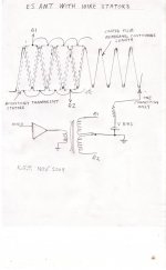
A new idea
In the drawing is depicted a stator type ES AMT where the stator has a special shape, and is acousticaly transparent. It could be perforated metal, wire or wire mesh. The membrane pattern is zig zag but the forces over the pleats are more even than if the stators were flat. There should be a lower percentage of air that cannot be moved compared to parallel pleats.
We come to the question of how to view it acousticaly. One way is to note that our "box of air" has become a "wedge of air", where for a given ammount of motion we have a pressure gradient in the pleat opening. For the situation where motor force is marginal perhaps we have a "half way house" between a flat radiator and a pleated one. It could also be viewed as a micro horn. The shape of the stator could mimic the catenary? curve that the pleats may assume to supply higher forces at the edges.
I figure that if you were to put some water in a bath and provide a flat surface below the water you could do the following--. Tape a pair of flat boards (wooden rulers) together at one end and lay them on the underwater surface. Add a polystyrene ball as an indication of fluid motion and move the boards. I think we should see the transformation from high velocity at the apex to a reduced velocity at the exit. Likewise the pressure should be transformed if we had seals top and bottom.
It won't have the acoustic energy per area of a parallel pleated design but breaks the nexus between pleat spacing and motor force? If we look at what is happening at the narrow end of the pleat opening during a compression the motor is not burdened with being a vacuum pump as well as a pressure pump to the degree it would be in a normal AMT. Construction should be simpler than the all moving design with some interesting scope for varying the spacing by bodily moving the stator triangles and altering tension without loosing membrane contact. It seems to lend itself to a more midrange design.
Keith
An AMT tutorial
In the electro magnetic version the pleats are arrayed parallel to one another in space. That space has a magnetic field, where the flux is running parallel to the pleats. Any forces, and subsequent motion due to current being passed through conductors on the pleats will be at 90 degrees to the field. The thing to realise is that each pleat is subject to forces quite independantly of conditions in neighboring pleats. To do any useful work (move air) three sides of the pleats have to be sealed to the neigthboring pleats such that the opening alternates between front and rear. The seal can be as floppy as you like because it does not have to perform any "station Keeping" function for the pleats.
In an ES AMT things are quite different in that the forces are between adjacent pleats, and, in the case of bias; exist continuously whether audio is being applied or not. OK, we know that in the perfectly centred case bias induced forces will cancel. It is just that we cannot rely on it and have to resort to tension. Apart from the necessity of tension the inter-pleat spacing method prevents us from achieving the the air displacement that a floppy seal allows. There are pockets of "dead air" abutting the posts.
A new idea
In the drawing is depicted a stator type ES AMT where the stator has a special shape, and is acousticaly transparent. It could be perforated metal, wire or wire mesh. The membrane pattern is zig zag but the forces over the pleats are more even than if the stators were flat. There should be a lower percentage of air that cannot be moved compared to parallel pleats.
We come to the question of how to view it acousticaly. One way is to note that our "box of air" has become a "wedge of air", where for a given ammount of motion we have a pressure gradient in the pleat opening. For the situation where motor force is marginal perhaps we have a "half way house" between a flat radiator and a pleated one. It could also be viewed as a micro horn. The shape of the stator could mimic the catenary? curve that the pleats may assume to supply higher forces at the edges.
I figure that if you were to put some water in a bath and provide a flat surface below the water you could do the following--. Tape a pair of flat boards (wooden rulers) together at one end and lay them on the underwater surface. Add a polystyrene ball as an indication of fluid motion and move the boards. I think we should see the transformation from high velocity at the apex to a reduced velocity at the exit. Likewise the pressure should be transformed if we had seals top and bottom.
It won't have the acoustic energy per area of a parallel pleated design but breaks the nexus between pleat spacing and motor force? If we look at what is happening at the narrow end of the pleat opening during a compression the motor is not burdened with being a vacuum pump as well as a pressure pump to the degree it would be in a normal AMT. Construction should be simpler than the all moving design with some interesting scope for varying the spacing by bodily moving the stator triangles and altering tension without loosing membrane contact. It seems to lend itself to a more midrange design.
Keith
Attachments
Michael, with my construction, where membrane contact is via the posts adjustment of tension is not something I have much control over. If tension is too small we loose contact and it stops working. I would not disagree that your spreadsheet is in need of some debugging. I could be missing something, but when I reduce the audio voltage to zero we are still getting a huge SPL figure!
Keith
Though I have not done any debugging at this point . there is a new - and now almost completed - version available I have uploaded today (091001)
Maybe you still are a little bit confused that I claculate *two* SPL figures – let me explain:
There are several brick wall SPL limits with ESL's
1.) SPL limitation due to limited Signal and Polarisation Voltages ("Perc of breakdown Voltage")
these limitations are addressed so that *if* you enter too high voltages for a given gap the corresponding fields turn RED. The maximum one can safely (and reliably) apply is determined by the break down voltage of air (arcing).
2.) SPL limitation due to limited gap width ("Full Gap excursion SPL")
this is a pretty easy to understand constant as it is the same as the mechanic x-max of dynamic speakers. The *SPL* you can reach depends on frequency (for the same max excursion)
You have to have the power to reach this limit though!!
3.) SPL limited due to current drawn ("Pow demand (100% Signal Voltage)")
Usually you have a certain amplifier or step up transformer wattage limit. If you push voltages too high or make areas too large – then you unavoidable will run into this limits.
These limits are addressed in that the fields "Pow demand (100% Signal Voltage)" turn into RED
4.) SPL Limit from too high Audio or Polarisation Voltage ("100% Signal Voltage SPL") with respect to the lowest frequency ("Low Frequency")
It is possible to stay within all former limits and nevertheless get too much excursion with respect to what your gap allows. This may occur in the lower frequency department where radiation impedance becomes very low.
To address this limitation the fields " Perc of Full Gap excursion" turn into RED
To sum up
The two numbers of SPL in my spreadsheet are for
1.) the purely mechanic determined SPL limits of your design and
2.) for the operational determined SPL limits
I could be missing something, but when I reduce the audio voltage to zero we are still getting a huge SPL figure!
Keith
As outlined – the pure mechanic X-max SPL limit is there even when you turn your voltages down
😉
Please report back if it doesn't turn out right for you
An AMT tutorial
In the electro magnetic version the pleats are arrayed parallel to one another in space. That space has a magnetic field, where the flux is running parallel to the pleats. Any forces, and subsequent motion due to current being passed through conductors on the pleats will be at 90 degrees to the field. The thing to realise is that each pleat is subject to forces quite independantly of conditions in neighboring pleats. To do any useful work (move air) three sides of the pleats have to be sealed to the neigthboring pleats such that the opening alternates between front and rear. The seal can be as floppy as you like because it does not have to perform any "station Keeping" function for the pleats.
In an ES AMT things are quite different in that the forces are between adjacent pleats, and, in the case of bias; exist continuously whether audio is being applied or not. OK, we know that in the perfectly centred case bias induced forces will cancel. It is just that we cannot rely on it and have to resort to tension. Apart from the necessity of tension the inter-pleat spacing method prevents us from achieving the the air displacement that a floppy seal allows. There are pockets of "dead air" abutting the posts.
Keith
I'm well aware of the principle and of the mechanics involved – I currently use my second generation of AMT's – knowing them inside and outside and even a little bit more
😉
I'm fascinated by your design because it seems o be possible to overcome the lowish SPL limits of general ESL's.
Key here is pleat "depth to width factor" nothing else!
We will see if this is eaten up by the additional radiation impedance load once your prototype is up and working – really hope not...
A new idea
In the drawing is depicted a stator type ES AMT where the stator has a special shape, and is acousticaly transparent. It could be perforated metal, wire or wire mesh. The membrane pattern is zig zag but the forces over the pleats are more even than if the stators were flat. There should be a lower percentage of air that cannot be moved compared to parallel pleats.
We come to the question of how to view it acousticaly. One way is to note that our "box of air" has become a "wedge of air", where for a given ammount of motion we have a pressure gradient in the pleat opening. For the situation where motor force is marginal perhaps we have a "half way house" between a flat radiator and a pleated one. It could also be viewed as a micro horn. The shape of the stator could mimic the catenary? curve that the pleats may assume to supply higher forces at the edges.
I figure that if you were to put some water in a bath and provide a flat surface below the water you could do the following--. Tape a pair of flat boards (wooden rulers) together at one end and lay them on the underwater surface. Add a polystyrene ball as an indication of fluid motion and move the boards. I think we should see the transformation from high velocity at the apex to a reduced velocity at the exit. Likewise the pressure should be transformed if we had seals top and bottom.
It won't have the acoustic energy per area of a parallel pleated design but breaks the nexus between pleat spacing and motor force? If we look at what is happening at the narrow end of the pleat opening during a compression the motor is not burdened with being a vacuum pump as well as a pressure pump to the degree it would be in a normal AMT. Construction should be simpler than the all moving design with some interesting scope for varying the spacing by bodily moving the stator triangles and altering tension without loosing membrane contact. It seems to lend itself to a more midrange design.
Keith
Nice idea !
But allow me to repeat that I think you are too much worried with the "aerodynamics" – this is quite different with waves...
Worst scenario you get is what could be subsumed as "added air mass" – and as outlined – a ten times the membrane mass let your SPL drop by 20dB – very easy to predict...
Michael
Last edited:
New wedge concept
I think your new idea is very clever. Although it presents some daunting fabrication challenges, it would seem more apt to produce waves that can travel out.
I think your new idea is very clever. Although it presents some daunting fabrication challenges, it would seem more apt to produce waves that can travel out.
Hi,
jauu
Calvin
Everything has imits.....and sufficiently high SPLs can be reached with general ESL design. AMT does nothing else but reducing size. That this won´t come without compromising on other parameters should be obvious.I'm fascinated by your design because it seems o be possible to overcome the lowish SPL limits of general ESL's.
jauu
Calvin
Everything has imits.....and sufficiently high SPLs can be reached with general ESL design. AMT does nothing else but reducing size.
There is what would be an advantage under some conditions to reducing the radiating area for a given SPL -- wider dispersion. Also, simply making the baffle more compact might be a good thing. Alternatively, getting more SPL from a given area may also be appealing, although it would come with the same high capacitance that the folded up area would have if unfolded.
That this won´t come without compromising on other parameters should be obvious.
I think most people grasp the fact that trade-offs exist, but not all are aware of what they are at the onset of a brainstorm. Even experienced engineers should regularly allow themselves to postpone considerations of practicality, at least to some extent. Amateurs and experts operating in this mode can and do get intriguing and potentially useful basic ideas. Then during the process of evaluating those ideas, they apply or gain expertise that may or may not lead to alteration or rejection. Any expertise gained will benefit future thinking, and may put a person partway down a road that no one has traveled before. This is the basis for much original work.
Hi,
Everything has imits.....and sufficiently high SPLs can be reached with general ESL design. AMT does nothing else but reducing size. That this won´t come without compromising on other parameters should be obvious.
jauu
Calvin
jauu Calvin, do you find at least my spread sheet useful to some degree ?
Michael
Cheer up
Thinking about the impacts of the ESAMT design and reading a lot valuable sharing’s in ESL threads, and also extensively consulting my own spreadsheet – I found some good reasons not so obvious for me at first to continue with your invention Keith.
1.) I have come to the conclusion that stability in the sense of collapsing pleats is a non-issue. Compared to a standard ESL there is basically no difference in the condition of stability versus film tensioning. Worst case scenario IMO is that you end up with doubling the tension to keep stability - thus most ill result would be doubling the lowest possible resonance frequency. No big deal IMO.
2.) Thinking about additional air mass that loads the ESL when folded to an ESAMT I think this can be seen as a net positive effect. For the upper frequencies it does no harm as is obvious when we look at large single panel normal ESL’s that don’t suffer from large areas in the upper range *from principle*. The beauty of ESL’s actually is that the additional load due to greater radiating area is balanced by the stronger motor (as long as we can afford the higher power demand of course, and also keeping in mind the pleat depth lamda /4 limit). Practical limits like directivity (beaming) are even in advantage for folded ESL. As for the lower frequencies the higher load – per front area – should have the effect to more efficiently dampen the F-res peak – again, equal front areas compared to each other.
3.) Once folded ESL gets in size towards full range speaker there is a benefit in that no additional spacers are required to insure film stability over large radiating areas.
4.) Last but not least - to put out more SPL per front area is a benefit by its own of course
To sum up I see no big drawbacks in the upper frequency range (besides the lamda /4 limit that we do not have with standard ESL’s) but a serious advantage in the lower frequency range.
To get way better loading at the low end is an huge advantage IMO, as ESL’s have their weakest spot there.
As for possible ill effects of flow resistance when the pleat depth to width ration increases, my guts feeling form what I did in sectoring horns and what I see from phase plugs for compression drivers I would really be surprised if these effects seriously would enter the picture below - say - a factor of 10.

Michael
Thinking about the impacts of the ESAMT design and reading a lot valuable sharing’s in ESL threads, and also extensively consulting my own spreadsheet – I found some good reasons not so obvious for me at first to continue with your invention Keith.
1.) I have come to the conclusion that stability in the sense of collapsing pleats is a non-issue. Compared to a standard ESL there is basically no difference in the condition of stability versus film tensioning. Worst case scenario IMO is that you end up with doubling the tension to keep stability - thus most ill result would be doubling the lowest possible resonance frequency. No big deal IMO.
2.) Thinking about additional air mass that loads the ESL when folded to an ESAMT I think this can be seen as a net positive effect. For the upper frequencies it does no harm as is obvious when we look at large single panel normal ESL’s that don’t suffer from large areas in the upper range *from principle*. The beauty of ESL’s actually is that the additional load due to greater radiating area is balanced by the stronger motor (as long as we can afford the higher power demand of course, and also keeping in mind the pleat depth lamda /4 limit). Practical limits like directivity (beaming) are even in advantage for folded ESL. As for the lower frequencies the higher load – per front area – should have the effect to more efficiently dampen the F-res peak – again, equal front areas compared to each other.
3.) Once folded ESL gets in size towards full range speaker there is a benefit in that no additional spacers are required to insure film stability over large radiating areas.
4.) Last but not least - to put out more SPL per front area is a benefit by its own of course
To sum up I see no big drawbacks in the upper frequency range (besides the lamda /4 limit that we do not have with standard ESL’s) but a serious advantage in the lower frequency range.
To get way better loading at the low end is an huge advantage IMO, as ESL’s have their weakest spot there.
As for possible ill effects of flow resistance when the pleat depth to width ration increases, my guts feeling form what I did in sectoring horns and what I see from phase plugs for compression drivers I would really be surprised if these effects seriously would enter the picture below - say - a factor of 10.
Michael
Coulomb's Law and breakdown
I'm not sure about your wording about balancing the breakdown voltage, but you are right about Coulomb's Law not being the problem that I wrote it was. I even know better from both experience and arithmetic, but had a brain fart. Sorry everyone. Please do not pose the obvious, embarrassing questions.
To review correctly, force is proportional to the product of the bias and drive voltages, and inversely proportional to the square of the gap width. Along the lines of what Michael pointed out, it can be arranged that the bias and drive voltages are both doubled for a doubling in gap width, whereby any increase in gap is entirely made up for. There are other factors, but this holds true at least when considered in isolation.
Not exactly the case, as you can increase signal voltage *and* polarisation voltage – which balances with the breakdown voltage.
I'm not sure about your wording about balancing the breakdown voltage, but you are right about Coulomb's Law not being the problem that I wrote it was. I even know better from both experience and arithmetic, but had a brain fart. Sorry everyone. Please do not pose the obvious, embarrassing questions.
To review correctly, force is proportional to the product of the bias and drive voltages, and inversely proportional to the square of the gap width. Along the lines of what Michael pointed out, it can be arranged that the bias and drive voltages are both doubled for a doubling in gap width, whereby any increase in gap is entirely made up for. There are other factors, but this holds true at least when considered in isolation.
AMT Parameters
Have you written one for Heil's magnetostatic AMT, Michael? It would be great to get a feel for the membrane forces for that case.
to make things simple for you guys, I started to put together a spreadsheet
Have you written one for Heil's magnetostatic AMT, Michael? It would be great to get a feel for the membrane forces for that case.
Michael, I agree with much of what you are saying. We really need to explore f factors of 10 or more otherwise we might as well give up because we are stuck with a situation where we have a spacing and excursion capability that we cannot use because the resonance is too high. I have a feeling air mass loading is not going to be the problem that spring loading obviously is. I also believe that closing the pleat ends is going to lower the resonance.
When we consider guideline suggestions for normal ESL span to spacing ratios of around 100 (Sanders); 10 is a modest figure. My next move will be to build a deliberately oversize pleat depth to try and answer two questions.
Is air mass loading a problem?
Where is the upper cut off frequency?
The "AMT tutorial" was not aimed at anyone in particular; just thinking aloud!
The mention in an earlier post of zig zag pleats allowing a continuum from flat to pleated should have had the qualification Provided the pleats are acoustically small In the realms of impracticality, if we take a flat radiator powered by means that are irrelevant, and segment it into small pleats with hinges, we could concertina it between flat and fully closed. This would change the f factor from 0?, 1? to infinity. Any dissagreement?
Keith
Aspect ratio trial
I think it will be instructive to try approaching a solid surface with a planar ESL panel while it produces pink noise. Maintaining the panel parallel to the surface will illuminate one set of things, and trying it at different angles will illuminate another, and varying the area of the solid surface will produce additional results.
If you don't have one, and can not get one easily or cheaply enough, one can be made that is good enough for this test using two small panels of perforated sheet metal as stators, some strips of plastic, and some contact adhesive. Cut one corner from each stator to allow a clear connection to the opposite panel. Insulate and reinforce the membrane with PET tape along the edge where you bring it out for the bias connection. Tape the outsides of all edges with at least two layers of PET tape to protect yourself from the signal while handling the panel. (If you have not yet felt the signal during your AMT trials, trust that you have enjoyed the preferable alternative.) Use a pair of washers in contact with the protruding bit of membrane to make the bias connection and clamp them together with a clip lead or some better method of your own devising.
If your film is biaxially oriented, you can probably tension it adequately using hot air after gluing it to the spacers. If not, I read of an interesting method some time back where the film is taped down over a small table with a big hole in it that has a bicycle inner tube laid upon it, and the inner tube then inflated. The stator with its spacers already coated with adhesive is brought down onto the now tight membrane, and voilà.
My next move will be to build a deliberately oversize pleat depth . . .
I think it will be instructive to try approaching a solid surface with a planar ESL panel while it produces pink noise. Maintaining the panel parallel to the surface will illuminate one set of things, and trying it at different angles will illuminate another, and varying the area of the solid surface will produce additional results.
If you don't have one, and can not get one easily or cheaply enough, one can be made that is good enough for this test using two small panels of perforated sheet metal as stators, some strips of plastic, and some contact adhesive. Cut one corner from each stator to allow a clear connection to the opposite panel. Insulate and reinforce the membrane with PET tape along the edge where you bring it out for the bias connection. Tape the outsides of all edges with at least two layers of PET tape to protect yourself from the signal while handling the panel. (If you have not yet felt the signal during your AMT trials, trust that you have enjoyed the preferable alternative.) Use a pair of washers in contact with the protruding bit of membrane to make the bias connection and clamp them together with a clip lead or some better method of your own devising.
If your film is biaxially oriented, you can probably tension it adequately using hot air after gluing it to the spacers. If not, I read of an interesting method some time back where the film is taped down over a small table with a big hole in it that has a bicycle inner tube laid upon it, and the inner tube then inflated. The stator with its spacers already coated with adhesive is brought down onto the now tight membrane, and voilà.
Last edited:
- Home
- Loudspeakers
- Planars & Exotics
- Electrostatic AMT?