If four combs were to form the pleat. Front top, Front bottom, Rear Top, Rear bottom.
You could conduct all four necessary drive signals to the pleats with minimal complexity.
Each comb need be energized with only one signal...
If you've already etched assuming two sided rods, no sense starting over. But if it turns
out a mess, maybe an idea for a second trial?
You could conduct all four necessary drive signals to the pleats with minimal complexity.
Each comb need be energized with only one signal...
If you've already etched assuming two sided rods, no sense starting over. But if it turns
out a mess, maybe an idea for a second trial?
Kenpeter, not certain that I follow you. Do you mean the four combs will be something to wrap the membrane around instead of posts, or in addition to posts. Because I am using conductive and resistive pleats I have only one contact per post as it is.
Still learning things about making the membrane. Found that I could not make contact with the metalisation after etching. At first I thought it may have had a layer of oxidation on it but it seems it was a layer of the sticky substance from the masking tape. It returned to normal when cleaned with methylated spirits and meth's seems to remove the bits of double sided tape that caused me trouble. A surprise was to find that one metalised pleat had no contact between one half and the other because there was a crease running through it. Apparently the caustic soda got in the tiny gap and etched a track that is too small for me to see, even with a magnifying glass. After etching the membrane took on a cupped shape, but it seems to flatten when under tension in the baffle.
Another problem discovered when lacing up the membrane, post etching is that it is hard to see the transition from Mylar to metal to check where it is in relation to the posts. the shiny metalisation and shiny posts all look the same.
Keith
Fab thoughts
I think he means that you might save some trouble in assembly by fabricating four identical sets of posts (combs), where each comb would carry one of your signals or polarizations. After lacing, each set of connections to the membrane would need only one connection to its source. To avoid mechanical interference, these could be arranged so that two are pointing downward, and two upward.
Try mixing [a lot of] lampblack into a vial of nail polish (after pouring some out or using some to make someone pretty), to the point that it is thickened but not a paste. You can find lampblack (aka, acetylene black, carbon black) as a "true black" pigment in hobby, craft or art shops. The result is not very conductive, but more than conductive enough in a thin coating for high voltage/low current. I think you could make your posts more visible by painting them with it. Test the conductivity before you use it, of course, to make sure you got enough carbon into the stuff.
Kenpeter, not certain that I follow you. Do you mean the four combs will be something to wrap the membrane around instead of posts, or in addition to posts. Because I am using conductive and resistive pleats I have only one contact per post as it is.
I think he means that you might save some trouble in assembly by fabricating four identical sets of posts (combs), where each comb would carry one of your signals or polarizations. After lacing, each set of connections to the membrane would need only one connection to its source. To avoid mechanical interference, these could be arranged so that two are pointing downward, and two upward.
Another problem discovered when lacing up the membrane, post etching is that it is hard to see the transition from Mylar to metal to check where it is in relation to the posts. the shiny metalisation and shiny posts all look the same.
Try mixing [a lot of] lampblack into a vial of nail polish (after pouring some out or using some to make someone pretty), to the point that it is thickened but not a paste. You can find lampblack (aka, acetylene black, carbon black) as a "true black" pigment in hobby, craft or art shops. The result is not very conductive, but more than conductive enough in a thin coating for high voltage/low current. I think you could make your posts more visible by painting them with it. Test the conductivity before you use it, of course, to make sure you got enough carbon into the stuff.
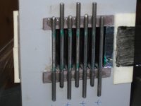
Thanks David, I now understand the combs. I have stood the posts away from the baffle so I can make a plug connection to them so this should not be a problem. If I cannot find a plug, wire wrap may be an alternative. Soldering seems definitely out. Found cutting the membrane with a straight edge and a razor blade vastly preferable to sizzors. Also proper masking tape with moderate stickiness performed better than office tape for etching.
Having just applied resistive coating to membrane attempt number two things are progressing. I applied the coating freehand using a foam brush rather than using masking tape. There are a couple of insulation hot spots where the conductive pleats exit the bias posts and where the resistive pleats exit the audio drive posts. In these places I have a triangle of bare Mylar in each corner.
Keith
If I cannot find a plug, wire wrap may be an alternative. Soldering seems definitely out.
How about just a bunch of clip leads, just to get started?
How about just a bunch of clip leads, just to get started?
Actually, since you do not need a high current connection, the following should do the trick: strip a goodly amount of insulation from each wire, loop the bare wire around each post, and twist it onto itself. You could even tack these loops in place using the conductive nail polish, if you made some, or solder the twisted part to itself.
BTW, it is worth being aware that vinyl insulation is conductive enough to let some charge through at high voltage. You might have noticed the occasional unexpected tickle. It also does not have very high dielectric strength, so don't rely on it to keep you safe from the signal voltage. Fluorinated polymers give the best isolation, and Teflon (PTFE) is best.
Last edited:
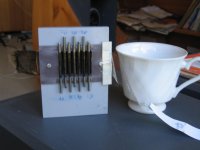
Thanks for the ideas David. I think the comb idea would not be good for a prototype; as with separate pleat access finding leakages and shorts will be much easier by being able to unplug them one at a time. If we have one or two faulty pleats we could abandon them in the interests of getting one group of four working. The device is none too elegant aesthetically. That is part of the back of an Orion dipole in the background.
Keith
Keith
Attachments
Wow! Thats encouraging news. Do you mean enhanced sensitivity of the pleated diaphragm (when pleated) compared to an ordinary ESL of equivalent size, or do you mean the area of the unwrapped AMT for the same area of ESL? Sorry to be testing your English language skills. Do you speak Russian?
Keith
No problem, I have to practicise English, haven't done that for half of a year, time passes quickly, knowledge passes even faster. 🙁 Yes, I speak Russian.
Here is the link to exact post about higher sensitivity. I've read the thread a long time ago, and much has been posted there since then, but as far as I remember, it's a 20 cm wide * 10 deep * 7 layer construct, I don't know spacing though, and from that post it seems that he exactly means higher sensitivity of pleated diaphragm, as he's referring to previous post, where lots of theory is written. There, ESL-AMT are intended for ultra-bass, having unmatched volume excursion, not as fullrange emitters though.
Sorry for the delay, didn't have any time..
Progress!
If it were, you would have been wasting time making it that way. I think your apparatus is very cool, Keith! Good thinking about isolating the connections on the prototype.
Oh, FWIW, I think I was remembering back incorrectly about that QAD conductive dope. I think you would have to use graphite, which is not as easy to get. The dry graphite powder that is used for lock lubrication might work, though.
The device is none too elegant aesthetically. Keith
If it were, you would have been wasting time making it that way. I think your apparatus is very cool, Keith! Good thinking about isolating the connections on the prototype.
Oh, FWIW, I think I was remembering back incorrectly about that QAD conductive dope. I think you would have to use graphite, which is not as easy to get. The dry graphite powder that is used for lock lubrication might work, though.
Here is the link to exact post about higher sensitivity.
Thanks, Nevod. I tried following this link, though, and got an isolated entry that babelfish translates to English as posted earlier.
Here is a link to the that thread starting at its root page: http://www.audioportal.su/forums/showthread.php?t=11841
The first message translates [literally] as:
Title:On silence the production of electrostatic AC
Author's name: Valeriy Ivanovich
Text: As to gather electrostatic loudspeaker under the household conditions. That it is necessary to know for this. What technologies to use under the household conditions.
Valeriy's next posting seems to be a translation into Russian of RTR's notes on ESL prototyping. I have no idea where the ES-AMT woofer design is analyzed, among the 76 (yep!) pages of postings to thar thread.
Nevod, if you could find and tell us which page the ES-AMT topic is first raised on, that would be great.
FWIW, I don't speak Russian, but I know one thing: Za vashe zdrodovie.
Last edited:
The verdict
Hi all, today was crunch time for the prototype ES AMT. Firstly I turned on the bias supplies and no smoke, no arcing, and no membrane instabilty. Next I applied the bias supplies to the audio pleats as a way of testing them for leakages etc. No problems observed and no leakage between audio and bias pleats as far as could be read on a 20K per volt moving coil multimeter. Somewhere in the proceedings I had missidentified the two classes of pleats and after sorting this out audio was applied.
Sadly, the SPL emitted was very feeble indeed, so much so that I abandoned ideas of getting an SPL measurement at 1 metre because it was below the level of distant low frequency noises from traffic etc. The open top and bottom ends of the membrane have not been sealed as that prevents any removal of the membrane. I have the impression that doing this is not going to make a huge difference to the sensitivity. As the bias supplies are plus and minus 3kV there could be something to gain by upping these, but I will have to make/buy another supply. I have no way of measuring the coated pleat resistivity or establishing whether the coating is in contact with all the bias posts. I did observe that the device continued to play for some time after switching off the bias supplies.
Had a think about an aspect that had crossed my mind previously, and it seems, with some justification. Presumably the coated pleats are not a Faraday shield?, opinions welcome. If this is so, and you draw out the polarities needed for AMT motion it can be seen that unwanted forces between adjacent audio (conducting pleats) are of a sign that tends to counteract the wanted motion. Will have to think about it a bit more. Maybe the stator ES AMT confers an advantage here?
The AMT was being fed with a full bandwidth signal even though I was using a tweeter power amp of the Orion system to drive it. On music there were some obvious resonances which may be tamed were the ends sealed. On tone I was reading around 1.5 kV P-P of audio. Winding up the audio level eventually produced arcing between adjacent posts, although not always in the same place. For such small spans of membrane it seems tension is a non issue. Never once did I see the membrane visibly move.
Keith
First crack at a prototype!
Congratulations on getting your apparatus built, Keith. Seems you are now at the debugging stage.
True, and practically no difference at high frequencies.
Air supports about 3 kV/mm, assuming no sharp points (no coronal ionization of the air). If I remember your gap width right, you could go quite a bit higher, but it's already high enough to get plenty of force, and not worth the trouble to go higher until basic functionality is attained. Also, the SPL increase you'd get from a bias increase is small compared to what you need at this point.
This is a problem, especially the second part. The design and theory could be perfect, but it would be operating single-ended if one of the signal pleats is not connected, or could have some other connection problem, and the result would be indistinguishable from what you are experiencing. I think you can assume that aluminum metalization is more than conductive enough (too conductive for the bias layers, but as I believe you decided, that is a minor compromise for prototyping purposes).
You might confirm the connections by putting a very large resistor in series with the bias supply, connecting it to a needle, connecting the post for each area under test to the opposite polarity, then in the dark, look for a heightened coronal discharge from the needle point when it gets close to the hopefully connected membrane surface.
Means that at least one polarity was operating.
No worries, here. Assuming the coatings are intact and connected, the field in each gap will be as you initially thought, and will lead to alternating repulsive and attractive forces as one goes from gap to gap.
Congratulations on getting your apparatus built, Keith. Seems you are now at the debugging stage.
The open top and bottom ends of the membrane have not been sealed as that prevents any removal of the membrane. I have the impression that doing this is not going to make a huge difference to the sensitivity.
True, and practically no difference at high frequencies.
As the bias supplies are plus and minus 3kV there could be something to gain by upping these, but I will have to make/buy another supply.
Air supports about 3 kV/mm, assuming no sharp points (no coronal ionization of the air). If I remember your gap width right, you could go quite a bit higher, but it's already high enough to get plenty of force, and not worth the trouble to go higher until basic functionality is attained. Also, the SPL increase you'd get from a bias increase is small compared to what you need at this point.
I have no way of measuring the coated pleat resistivity or establishing whether the coating is in contact with all the bias posts.
This is a problem, especially the second part. The design and theory could be perfect, but it would be operating single-ended if one of the signal pleats is not connected, or could have some other connection problem, and the result would be indistinguishable from what you are experiencing. I think you can assume that aluminum metalization is more than conductive enough (too conductive for the bias layers, but as I believe you decided, that is a minor compromise for prototyping purposes).
You might confirm the connections by putting a very large resistor in series with the bias supply, connecting it to a needle, connecting the post for each area under test to the opposite polarity, then in the dark, look for a heightened coronal discharge from the needle point when it gets close to the hopefully connected membrane surface.
I did observe that the device continued to play for some time after switching off the bias supplies.
Means that at least one polarity was operating.
. . . it can be seen that unwanted forces between adjacent audio (conducting pleats) are of a sign that tends to counteract the wanted motion.
No worries, here. Assuming the coatings are intact and connected, the field in each gap will be as you initially thought, and will lead to alternating repulsive and attractive forces as one goes from gap to gap.

Good start Keith - don't give up immediately
In addition to David's analysis and suggestions -
have you checked your membrane resonant frequency?
If it is too high, your output will will be in the cellar.
You possibly can check with a close mic and RTA software if you are somewhere in the 500Hz range I recommended earlier.
Just excite the membrane with a toothpick (no voltages applied) and see where your RTA shows the resonant frequency. You will need a silent place.
Michael
Last edited:
After a good sleep I think the problem lies in the conductive posts.
Remember why we said that the pleats *must* be in parallel at the beginning - same issue here - the conductive posts avoid the Q to be spread equally over the surface of the pleat - all (or most) Q is trapped at the closest point to a next audio voltage driven pleat that is close by due to the asymmetry of conducting by the posts.
No Q equally spread over the pleat - no force - simple...
Further - low resistance of the polarized pleat does not help here as well - quite in contrary (not the main issue though IMO)
Michael
After a good sleep I think the problem lies in the conductive posts.
Remember why we said that the pleats *must* be in parallel at the beginning - same issue here - the conductive posts avoid the Q to be spread equally over the surface of the pleat - all (or most) Q is trapped at the closest point to a next audio voltage driven pleat that is close by due to the asymmetry of conducting by the posts.
No Q equally spread over the pleat - no force - simple...
Further - low resistance of the polarized pleat does not help here as well - quite in contrary (not the main issue though IMO)
Michael
Checked back - forget what I posted - its not exactly that we get less Q this way - just that we get an additional Q reservoir connected by low resistance.
It would increase distortion as its no longer perfect *constant* Q operation but it should work nevertheless.
Leaves membrane tension to be the main issue IMO
Michael
Tension
Tension is not any concern when it comes to the basic making-sound-or-not paradigm, for the following reasons:
1) The resonant frequency mainly sets the lower cutoff.
2) Tensile force contribution to the total load can be considered insignificant above an octave over this frequency.
3) It will be impossible to apply so much tension that the resonant frequency occurs above 10 kHz, because the film will experience inelastic deformation several octaves below that frequency during the attempt (not to mention bending the posts).
Also, of course, anyone who reads what Keith wrote will have noticed that he is operating his device with minimal tension, which he correctly asserts is okay because there is no membrane collapse.
So, the device might be limited by tension to high frequencies, but certainly something audible.
have you checked your membrane resonant frequency?
Tension is not any concern when it comes to the basic making-sound-or-not paradigm, for the following reasons:
1) The resonant frequency mainly sets the lower cutoff.
2) Tensile force contribution to the total load can be considered insignificant above an octave over this frequency.
3) It will be impossible to apply so much tension that the resonant frequency occurs above 10 kHz, because the film will experience inelastic deformation several octaves below that frequency during the attempt (not to mention bending the posts).
Also, of course, anyone who reads what Keith wrote will have noticed that he is operating his device with minimal tension, which he correctly asserts is okay because there is no membrane collapse.
So, the device might be limited by tension to high frequencies, but certainly something audible.
Well - its you who has the experience here.
🙂
Ad 3 - did you count in that the dimension of the pleats are Veeeery small thus pushing resonance up considerably compared to more usual ESL dimensions?
Also the total area - if pleats are stretched - still is pretty small and the 2.8mm gap is unlikely to be anything close to a realistic excursion.
If we consider 0.1mm to be a realistic excursion we end up by several orders of magnitude lower SPL than mechanically possible.
Keith - if you have the possibility to measure I really would be interested in
1.) the resonant frequency of the membrane
2.) the capacitance between two pleats
Would possibly help to set up for some further calculations...
Michael
Thanks for the comments. Not being an ESL enthusiast/builder it comes as a bit of a surprise to learn of the limitations of multimeters (digital or otherwise) for making measurements of voltage and resistance found in the art. There are two aspects to the debugging process. One is debugging the theory and the other the implementation. David, I presume you mean holding a needle in your uninsulated fingers to see corona discharges to the coated pleats with audio disconnected. The 33meg resistors should limit the current to microamps. What about holding the ball on the end of a hat pin? 🙂 Looking into the pleats with bias only applied there were several fine strands of fluff standing on end as if charged.
I have not grounded the audio transformer CT. When first powered up with 2 kHz tone applied there was a 100Hz (Aust 50Hz mains) ripple intermodulating with the tone even though the 100Hz was inaudible. This later went away and was presumably due to one or both bias supplies being loaded due to leakage paths. The supplier of the conductive coating suggests that it needs a few days to cure in which time the resistivity goes up, so much so that it becomes difficult to measure, which is one of my problems.
The audio drives are from low impedance sources whereas the bias supplies are current generators by dint of the series resistors. In the presence of inter pleat leakage paths the bias supplies are more likely to be modulated with audio than vice versa. Once again these unwanted signals are in a sense that degenerates sensitivity. Armed with the foregoing I devised a test method. Using a dual input oscilloscope set to differential mode, and with bias turned off I set a reference HV audio level across the transformer. Then, transfering the probes to the bias supplies, unwanted audio modulation could be seen. I found that the negative bias supply was being modulated with audio at 20% of reference. By disconnecting pleats I found two were contributing about equally to the problem. When these were disconnected and bias reapplied with no audio, the bias, for the first time started arcing between posts. It is a bit of a mystery why it arcs between two smooth? surfaces 2.8mm apart.
I am yet to be convinced that the biased pleats are doing much as I accidentally shorted the audio posts with bias off and got around the same SPL as with bias on?. System resonance seems to be around the 2kHz region. When arcing is occurring it can excite the pleat resonance. To date it seems long held reservations about the low compliance (strong spring) load on the motor are a dominant factor in restricting motion so that we do not get to the stage of making pronouncements about the air mass loading.
Keith
Last edited:
Thanks for the comments. Not being an ESL enthusiast/builder it comes as a bit of a surprise to learn of the limitations of multimeters (digital or otherwise) for making measurements of voltage and resistance found in the art.
Yes, you need at least two special bits: a surface resistivity meter and a static voltmeter. Assuming you achieve your basic proof of concept (POC), I would not venture further without them.
David, I presume you mean holding a needle in your uninsulated fingers to see corona discharges to the coated pleats with audio disconnected.
😉 A clip lead holds the pin and connects to the bias supply. You hold the insulated clip. You must have a bunch of clip leads . . .
Looking into the pleats with bias only applied there were several fine strands of fluff standing on end as if charged.
Fluff is not good. Surfaces should be fluff-free. 🙂
I have not grounded the audio transformer CT.
I remember thinking that your original schematic was correct.
The supplier of the conductive coating suggests that it needs a few days to cure in which time the resistivity goes up, so much so that it becomes difficult to measure, which is one of my problems.
Eh? I thought you were relying on metalization for all electrodes. At least, you must use high conductivity electrodes for the signals. Later, assuming you get POC, then comes the time to think about substituting a high resistivity coating for treating the polarized pleats. For this, there are lots of things that will work, but all should achieve their final value within hours.
By disconnecting pleats I found two were contributing about equally to the problem. When these were disconnected and bias reapplied with no audio, the bias, for the first time started arcing between posts. It is a bit of a mystery why it arcs between two smooth? surfaces 2.8mm apart.
Arcs will travel along surfaces much more easily than through open air. One of the keys to sustaining high voltage across electrodes is to lengthen the surface paths. This is, for instance, why the insulators that suspend high voltage power lines have annular ribs. It is also one of several confounding ingredients in the ES-AMT concept that I felt it was premature to mention, but one that I think could be overcome, assuming initial POC.
System resonance seems to be around the 2kHz region.
Should be fine for a tweeter.
What is your pleat depth, Keith? Somehow, I can not get it from looking back over the past entries.
To date it seems long held reservations about the low compliance (strong spring) load on the motor are a dominant factor in restricting motion so that we do not get to the stage of making pronouncements about the air mass loading.
I think the device is not yet debugged to the point that any pronouncements can be made about any operating parameter, including compliance, where "operating" is the operative term.
Although I did not mention it I now realise that the voltage between adjacent bias posts is 6kV (the sum of the two supplies). Perhaps the arcing over 2.8mm is not unexpected. David, the present construction is metalised areas for the audio and resistive coating for the biased areas. The second membrane was made in one evening. Masking,etching,cleaning and the application of the resistive coating. The pleat depth as measured from the outer radius of a bias post to the same place on the next audio post is 20mm. Of course not all of this is displaceable air due to the posts which are 2.8mm diameter. Thus the pleat width is 2.8mm. Tried persueing the inter- pleat leakage. Cleaned off some felt tipped pen marks after unwrapping part of the membrane and thought I had nailed it by pulling on one end of the membrane while observing the bias modulation. The leakage went away because the HV audio was beng shorted out!😱 The power amp seemed to be experiencing some dificulties as the speaker protection relay was operating and the SOAR protection may have been limiting power disipation in the output devices.
Keith
Keith
- Home
- Loudspeakers
- Planars & Exotics
- Electrostatic AMT?