No, you're looking for something that can supply 100mA for a mono amplifier or 200mA for a stereo amplifier.
Power Transformer(s)?
Ah, ok - re-reading the thread makes that clear...
So I thought I'd do a bunch more reading before asking my next question. Could I use a 230V, (non-centre-tapped) 350ma transformer, such as the Hammond 185E230, and four diodes instead?
Of course this would mean I'd need one or two other transformers for the heaters and Constant Current Sources, but this still seems cheaper than a (new) large transformer with three secondary windings...
- Jeremy
A 500VA 480VAC industrial transformer with 2 240V secondaries would easily meat your needs cheap. Tie the secondaries together for 480VCT. Then use a separate filament transformer.
Power Transformer(s)?
Tweeker - that's not a bad idea. 🙂 Why such a high VA rating though?
I'd better make sure I get this straight though - I tie the secondaries in series, and the point where I tie them together becomes the "0" in the 240-0-240 business?
Tweeker - that's not a bad idea. 🙂 Why such a high VA rating though?
I'd better make sure I get this straight though - I tie the secondaries in series, and the point where I tie them together becomes the "0" in the 240-0-240 business?
I went conservative here and assumed stereo. 250VA would be fine for mono. I recommended a high VA rating here for a couple reasons. Transformer VA ratings assume steady AC loads. Capacitor input filters cause higher peak and RMS currents, and a full wave rectifier only uses half of the transformer at a time. Also, industrial transformers can be had dirt cheap. A thermister might be a good idea on the primary.
Yes, be sure to observe polarity or you might get 0VAC.
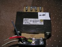
Pictured 1kVA 480VCT transformer already has the 2 240VAC secondaries tied together for 480VCT. The center tap is 0V. Cost almost as much to ship as to buy, I wish more people would use flat rate Priority Mail. I had a 40lb choke shipped from Pearl Harbor for $12 that way before.
I'd better make sure I get this straight though - I tie the secondaries in series, and the point where I tie them together becomes the "0" in the 240-0-240 business?
Yes, be sure to observe polarity or you might get 0VAC.
Pictured 1kVA 480VCT transformer already has the 2 240VAC secondaries tied together for 480VCT. The center tap is 0V. Cost almost as much to ship as to buy, I wish more people would use flat rate Priority Mail. I had a 40lb choke shipped from Pearl Harbor for $12 that way before.
Attachments
Yes, classic full wave rectifier is a pita looking at Xfrmer loading.
You may try the hybrid way:

The best of both technologies ? 😱 ?
Yves.
You may try the hybrid way:
The best of both technologies ? 😱 ?
Yves.
More Power Transformer
Sorry for the constant barrage of questions - I try to read a lot between each set at least...
I've managed to find a standard 240V transformer (not industrial) - 500mA. Would this be a suitable transformer? The HT only needs 200mA, is that right? Does a cap input filter really pull that much more current? I'm assuming it draws the most during a charge cycle? The reason I'm fixated on this one is because it's US$21...
Otherwise, I've found an industrial transformer. They seem to imply that the primaries are 480V, and the secondaries are 120V - step-down in other words. Would I need to hook this up "backwards"? I'm not positive this has 2x240V windings (guess I could write and ask) but it's US$35.
Yves - I'd like to try this at some point - I'll see if my transformers have the needed capacity... I've been looking at stats sheets - it looks like I'd need a 5U4 to pass along 200mA current, and the heater on this tube take 3A all by itself. (Am I reading this correctly? GZ34, 5Y3 don't supply enough current?)
Diomedian,
You may well get away with a Hammond Classic Series 260G.
This is 275-0-275 High Voltage at 200 mA with Filament windings as well (6.3V @ 5A and 5V @ 3A).
You may need a choke after the rectifier or a couple of power resistors in the HV leads before the rectifier diodes to drop a little voltage.
Cheers,
Ian
Power Transformer
ah - Thanks Ian, I don't know how I missed that one. 🙂
I was only able to find the 260G at a local dealer of all places (couldn't find it anywhere on the net). However, I found that it was more expensive than the 270HX at the same dealer - the 270HX is rated virtually the same: 275-0-275 200mA, 5V @ 3A, 6.3V @ 6A. The other nice thing about the 270HX is that it's one of Hammond's attractive "enclosed" series, so it should fit in nicely on the top of the chassis.
In terms of voltage, some quick back-of-the-envelope calculations say that if I use the circuit that Giaime proposed, I'll be left with about 308V on the B+. I'll veryify as soon as I can install a Windows emulator and Power Supply Designer... If I find I'm missing some dynamic range, I'll replace the voltage drop resistor with a 3-5H choke with another resistor if need be.
However! As there is still about a $24 air-gap between a 270HX and three separate small transformers, I may still go that route...
Jeremy
Jeremy,
Good to hear. Feel free to PM me when you get close to the set to work / fine tune phase. My experience with the 6V6 version suggested that I got better sound by ditching the global feedback and increasing the shunt feedback a bit. This is just a component change or two - mind you it had a lot more scope for improvement than the EL84 version as I was starting from a "darker" place.
The niece (Kristy) picks up the system I built for her, which includes the 6V6 version amp tonight so I won't have it to play with anymore and will be hooking up the EL84 version again on my system. If I have any fine tune hints for it I'll post them here.
My EL84 Version is running about +285 Volts on the B+ and I believe that a bit more volts (anything up to an absolute max of about +340 Volts would give a bit more omph! - ideal is around +300 to 320 Volts but with 10% mains voltage variation this will move around a lot)
ASIDE: I did some testing one Saturday afternoon recently when it was too hot to do much else - 37 degrees C, and everyone in the street had their airconditioners running - my HT was down by 20 Volts.
Cheers,
Ian
I’m new to DIY tube amps. I’m an EE, but all digital so far. My current gears are a Mark Levinson 331 amp, a Proceed AVP-S pre/pro, a pair of B&W 804 speakers (and a cheapo CD player). I was thinking about purchasing a tube amp. After reading the various message boards for purchase recommendations, I decided instead to build my own.
After a good bit of research on the web, I decided on the Baby Huey. It looks like an elegant design that’s simple enough for a newbie. I've gotten all the parts and I've built the CCS circuits. I’m ready to put the rest together. But I have a question about the power supply.
I've bought the Hammond 270FX power transformer. With 275-0-275, I figure I’ll need a couple of 470ohm resisters before the rectifiers to drop the voltage down to ~310v (assuming a 100mA load). Alternative, I am thinking about trying the LR8N3 based regulator on tech-diy (http://www.tech-diy.com/DIY_PWR_Preamp_HV.htm). It seems that the regulator is simple enough and it would let me adjust the output voltage easily by replacing R1 with a trimpot.
My question is: should I do that or stick with the basic PSU?
ctaudio said:With 275-0-275, I figure I’ll need a couple of 470ohm resisters before the rectifiers to drop the voltage down to ~310v (assuming a 100mA load).
My question is: should I do that or stick with the basic PSU?
I'd start with a basic supply. The dropping resitors go after the rectifier as part of a CRCRC network. (a choke in there is also a good thing).
dave
ctaudio,
My 2 cents worth - I don't believe a regulator is required. Since you are an EE might I suggest that if you have too much HT voltage then add a MOSFET gyrator (simulated inductor) before the final filter capacitor. That is an arrangement of Rectifier => first filter cap => MOSFET gyrator => final filter cap. That way you can get decent omph by keeping the final filter cap at a decent size (say 100uF or even 220uF) and adjust voltage by varying either the effective inductance value of the gyrator or the size of the first filter cap (or both). The simulated inductor will have the added benefit of absolutely scothing any rectifier switching noise.
B.T.W. that 100mA is per channel.
OR more SIMPLY put the dropping resistor immediately after the rectifier diodes in the feed to the filter capacitor. That way you only need one capacitor, you limit the ripple current in the capacitor (and hence improve it life expectancy) and limit the reverse switching current of the rectifiers and thus also reduce diode switching noise. Simple plus WIN WIN WIN. Actually I'm deciding as I type that this is a much better way to go - SIMPLE and elegant.
Good luck with it. I'm about to build a second one BUT this time I'm going to try a Hammond 1650E as the output tranny. Its a 15W rated unit rather than 10W of the Hammond 1608 and its physically as large as Hammonds 25W units. I think it will be less prone to transformer saturation at very low frequency.
Cheers,
Ian
Hi ctaudio,
I'm not an EE, and I'm a bit of a newbie myself, but I think I can answer. 🙂
There are a number of people on this board who have some pretty strong opinions against regulated B+ for tube amps, and as far as I can tell the reason is because tubes will work well with a great range of voltages, and you'll lose quite a bit of power to the regulator. (Overkill?)
Also, gingertube seems to think you'll need 100mA per channel (I don't know how to calculate this yet) - the 270FX may be a bit under-rated for stereo... The 270HX is maybe $15 more, supplies 200mA, supplies an extra 1A on the 6.3V secondary, and is otherwise the same. (Wouldn't you know it, he's chimed in already while I was writing this.)
Jeremy
Jeremy,
40mA idle current for each EL84 = 80mA, a few mA for the front end, a bit of allownace when you start to push the amp out of Class A into Class B (i.e when one side EL84 cuts off and the other side has peak current draw).
Say around 100mA per channel max. - if you occassionally draw 110 or 120 on peaks then the transformer won't mind.
Actually one thing to watch with HT over about 320V is power dissipation in the EL84s
Those 16 Ohms resistors in the emitter of the current sources give you 38mA idle current (not 40mA as stated above). 320V less 12V approx. at cathode x 38 mA = 11.7 Watts - dont go over 12 Watts. If you want to run a bit more conservatively with higher voltage than say 320V change the 16 Ohms to 18 Ohms to give you about 34mA instead.
Cheers,
Ian
I'm an EE, but I have not done anything that doesn't switch rail to rail since I graduated back in the original IBM PC days. That's what makes building my own tube amps appealing as a hobby. Designing computers and digital chips is just work now. I hope some analog will rekindle my love of electronics.
I'll try the dropping resister after the rectifier idea. (I have no idea what a gyrator is. It sounds interesting though. I'll need to research into it.)
BTW, I’m starting with just one channel now with budget parts to get a feel for things (grounding, etc). I’ve already bought the 270FX. I’ll get better parts and a bigger power transformer, or go monoblock, when I’m ready to build the amp for real.
ctaudio said:I have no idea what a gyrator is. It sounds interesting though. I'll need to research into it.
A gyrator is a kind of xfmr, except it transforms with negative coupling, so that a capacitive reactance at the primary becomes an inductive reactance with the same magnitude at the secondary (and vice versa). This requires op-amps as no passive device can do that. It's used quite frequently to make LC-type filters without those bothersome coils and all their problems: series resistance, stray capacitance, magnetic coupling to other circuits you'd rather not couple to.
Miles,
Gyrator - actually a gyrator does not need to be transformer based and I was'nt thinking of that kind. A gyrator can be made using any active device such as a transistor, opamp or mosfet.
See here for the basic idea:
http://www.epanorama.net/documents/telecom/gyrator.html
This would need to be scaled up using a power MOSFET for use as a simulated inductor in a power supply.
Cheers,
Ian
Fine tuning your EL84 Baby Huey
Back on the EL84 Version for final tweek last night.
1st tune the shunt feedback - the cross coupling resistor value.
A suitable test track for you "head banging" types was Track 15 off the compilation CD "Party Girls - Vol 4" - track is Bodyrockers "I like the way". This track starts off with vocals to the fore BUT the music very compressed and "backward". As the track progresses the music has the cpmpression progressively removed and it moves forward. Choose the feedback set resistor for a smooth slide from full back to fully forward. I ended up with 15K
2nd tune high frequency detail by adding a zobel (series Resistor and capacitor) across the secondary of the output tranny. Use resistor of 2 to 2.5 times the outut tap impedance, that is 10 Ohms for 4 Ohm output and add capacitance until there is no more apparent increase in high frequency content and detail. I ended up with 220nF.
Other useful test music
- Robert Palmer's "The Very Best of Robert Palmer" - great albumn, sounds great on good amps but sounds awful on bad amps.
and
Some female vocals - I use "Miss Chatelane" (spelling?) off KD Lang's "Ingenue" albumn.
Cheers
It's a Baby Huey!!
I finally finished building one channel of my Baby Huey over the weekend. I tested it with an old bookshelf speaker in the garage and it sounded great. Very quiet. There is a very faint hum audible only with my ear right up to the speaker. Not bad for a newbie, I thought.
Tonight I hooked the amp up to my B&W 804 speaker and it oscillates! There is a clear mid tone oscillation at 2-3KHz. I suspect it has something to do with the capacitance in the 12 foot long 10 gauge bi-wire speaker cables. I don't have an oscilloscope at home. I can borrow one from work. But how do I diagnostic this?
Other than this oscillation problem, I have another question regarding the PSU. I initially had the PSU hooked up as shown in the schematic with the exception of a voltage dropping resistor after the rectifiers. When I turn on the power switch, I'd blow the fuse pretty much every time (1A slow). I finally put in a HT switch that I switch on after the tubes warmed up. I initially thought the problem was related to the power on current into the caps, but I can see that the heaters would come on brighter than usual for a half a second on power up then settle back down to their normal brightness. What could be happening? Something to do with in rush current?
- Home
- Amplifiers
- Tubes / Valves
- EL84 Amp - Baby Huey