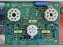
My EL34 Baby Huey will have its home soon, thanks to my friend Philippe that is doing the hard mechanical work that I am not able to do myself 😉 The top cover has been made by Front Panel Express, expensive but very good quality, the front and rear panels are made by Philippe, here are two pictures of the work, next step the front panel with two vu-meters !
Hi Marc,
What's the cost of top cover made by Front Panel Express?
Hello Marc:
Thanks for the idea I will try that this morning and report back.
Hopefully this will solve the concern
Thanks for the idea I will try that this morning and report back.
Hopefully this will solve the concern
hello again Marc:
I added a second 33k resistor to R39.
my meter readings are 880mv and 450mv for the test points. My bias input voltage is 60vac.
I do not think this is the solution to the problem.
I am wondering if I have the mosfets (Q5, Q6) in backwards?
Could you look at the photo of my board again to double check things.
Thank you again for the help.
A silk screen would have been useful to show which way around the transistors go.
I usually use a straight line to indicate the front of the transistor.
I usually use a straight line to indicate the front of the transistor.
Yes Nigel:
In order to mount the board to the chassis top panel and have access to the components I decided to load the board from the back. This has caused me a great deal of confusion, with a little help I should be able to get it sorted out.
Sorry for the rooky question.
In order to mount the board to the chassis top panel and have access to the components I decided to load the board from the back. This has caused me a great deal of confusion, with a little help I should be able to get it sorted out.
Sorry for the rooky question.
Hello Scott,
Sorry that this does not help, in fact the negative voltage is more critical with EL34, 6CA7 or KT88... For 6V6 a bias of -15 V is enough ( JJ Electronic - 6V6S ), therefor if you have 60 V AC, this mean that you should have about 80 V DC after the capacitor and it is more than enough.
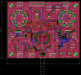
Now you will have to use your multi-meter and check the voltage on the output of R39, on the cursor of the two trimmers and finally on R11 and R12 where you should read between - 12 V and - 15 V... Try to adjust the trimmers to see the effect and don't forget that trimmer are on opposite side than test points (see attachement) 😕
Hi mravinsky,
The cost of the top panel from FPE is 111.90 € plus the taxes and the shipment 😡
As I said it's very expensive !
nigelwright7557,
The silk screen exist of course, it is on the top side, see picture 😀
Rgds,
Marc
Sorry that this does not help, in fact the negative voltage is more critical with EL34, 6CA7 or KT88... For 6V6 a bias of -15 V is enough ( JJ Electronic - 6V6S ), therefor if you have 60 V AC, this mean that you should have about 80 V DC after the capacitor and it is more than enough.
Now you will have to use your multi-meter and check the voltage on the output of R39, on the cursor of the two trimmers and finally on R11 and R12 where you should read between - 12 V and - 15 V... Try to adjust the trimmers to see the effect and don't forget that trimmer are on opposite side than test points (see attachement) 😕
Hi mravinsky,
The cost of the top panel from FPE is 111.90 € plus the taxes and the shipment 😡
As I said it's very expensive !
nigelwright7557,
The silk screen exist of course, it is on the top side, see picture 😀
Rgds,
Marc
Attachments
Thanks Marc:
the voltage between r39 and tp3 is -17.6 in and -7.6out
the voltage between r11 and tp3 is -23.5
the voltage between r12 and tp3 is -5.6
wiper on r41 is 0.0, turning does not change value
wiper on r42 is -7.0,turning changes value
when measuring across the pins of the trimmers I get 25k rather than 50k as indicated on the packaging of the trimmer. Could this be the problem. I am thinking I got faulty trimmers??
As a note I also had the BC547B transistors. I did not catch it till after i was testing .I replaced these perhaps the trimmers were damaged during that testing?
I decided to order the trim pots, the zener diodes, and the mosfets.
My initial testing with the BC547B transistors is likely the source of the trouble.
I should know for sure in a couple of days. Digikey is quite quick
I decided to order the trim pots, the zener diodes, and the mosfets.
My initial testing with the BC547B transistors is likely the source of the trouble.
I should know for sure in a couple of days. Digikey is quite quick
The voltage between R28 and R39 (Vbias on the schematic) should be about -80 V !
There is something wrong on your board, may be a cold solder ?
Beside that the BC547B will not survive at 80 V and the pinout is not compatible with the 2N5551, see post 2018 which explain the problem already found by papavienneau... 🙁
I hope the changes will solve your problem 🙂
I go to sleep now,
Cheers,
Marc
Hey guys! Just a quick update. My amp is working and sounds good. I am able to set the output tubes current and everything is stable. The problem is the 12AX7's.
I have around 70v on one plate and the other has around 160v on it. I have double checked the plate resistors and they are identical. The current source in the cathode should ensure balance though right? The pot in the cathode does absolutely nothing when I turn it.
Any ideas as to what could be happening?
with regard to Q5 and 6. Are there alternatives ?
these are the items.
STMicro STU9HN65M2
On Semi FQFP2N60C
Postage from Mouser to Malaysia prohibitive
thanks
these are the items.
STMicro STU9HN65M2
On Semi FQFP2N60C
Postage from Mouser to Malaysia prohibitive
thanks
Hey guys! Just a quick update. My amp is working and sounds good. I am able to set the output tubes current and everything is stable. The problem is the 12AX7's.
I have around 70v on one plate and the other has around 160v on it. I have double checked the plate resistors and they are identical. The current source in the cathode should ensure balance though right? The pot in the cathode does absolutely nothing when I turn it.
Any ideas as to what could be happening?
I had similar issues. Marc suggested I double up resistor 39 ( ie 2@33k resistors because it is easier than replacing it with an 18K to bring things down a bit and allow pots R41, R42 to balance the voltage on the driver plate. look back a few notes and he references the original discussion.
I hope this helps
McTavish,
The current source in the cathodes of the 12AX7 triodes ensures AC balance ONLY (if the current source is working).
The Pot in the cathodes should allow you to balance the DC operating point unless the two triode sections are quite different.
Check that both triode sections have good DC grid connection to 0V (the grid stop resistors and then the grid leak resistors).
IF good - try another 12AX7.
Then finally check the current source is working and that the pot itself is not faulty.
R39 should have nothing to do with this issue- it just sets the bias range for the output tubes which you say is OK.
Cheers,
Ian
with regard to Q5 and 6. Are there alternatives ?
these are the items.
STMicro STU9HN65M2
On Semi FQFP2N60C
Postage from Mouser to Malaysia prohibitive
thanks
Dear All,
some help is much appreciated
Hi kp93300,
1/2 watt resistors should be fine to sub for the 0.6 watt types. I'll often use the 0.6 watt types because the 1/2 watt one isn't available, or I'm just allowing more headroom. 100 mW isn't going to make a big difference, else they should have used a 1 watt.
-Chris
1/2 watt resistors should be fine to sub for the 0.6 watt types. I'll often use the 0.6 watt types because the 1/2 watt one isn't available, or I'm just allowing more headroom. 100 mW isn't going to make a big difference, else they should have used a 1 watt.
-Chris
ALTERNATIVE MOSFET AT Q5 AND 6
http://my.element14.com/vishay/irfi...-5-5a-to-220fp/dp/8649073?st=MOSFET n CHANNEL
http://my.element14.com/stmicroelec...-5-5a-to-220ab/dp/2807308?st=MOSFET n CHANNEL
Are these 2 mosfet good replacement for the recommended N channel mosfet stated in the BOM ??
http://my.element14.com/vishay/irfi...-5-5a-to-220fp/dp/8649073?st=MOSFET n CHANNEL
http://my.element14.com/stmicroelec...-5-5a-to-220ab/dp/2807308?st=MOSFET n CHANNEL
Are these 2 mosfet good replacement for the recommended N channel mosfet stated in the BOM ??
- Home
- Amplifiers
- Tubes / Valves
- EL84 Amp - Baby Huey