Hello Toriversen:
Thanks for the heads up about Ac grounding of the shield when using a 6n2p driver.
Thanks for the heads up about Ac grounding of the shield when using a 6n2p driver.
Hi potepuh,
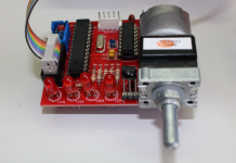
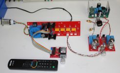
R7/1 and R7/2 are not trimmer but volume pot, any value between 20 k to 50 k log will be OK. Please note that there is two possibilities : on board pot or external motorized pot (see pictures)...
R7/1 and R7/2 are not trimmer but volume pot, any value between 20 k to 50 k log will be OK. Please note that there is two possibilities : on board pot or external motorized pot (see pictures)...
Attachments
If i have standalone preamp as the 10 times voltage with vol control. Then how can i modify this pot so i only use it as power amp purpose ? Shoul i bypass it or replace with the fixed value resistor ?
I bought some boards from the original group buy and finally will build them. I see many attachments for the construction of the amp, etc. I cannot find the schematic of the boards. Where is it?
I think it is in one of the previous post's attachment.I bought some boards from the original group buy and finally will build them. I see many attachments for the construction of the amp, etc. I cannot find the schematic of the boards. Where is it?
Attached is what I have downloaded to my computer, not sure there is a newer version of not.
Attachments
Hi ckwong99,
You can leave the pot and use it like a level trimmer to adjust both channel at the maximum value or close to that if you need to correct the balance between the channels.
Of course, you can also replace it with a 20 to 50 k resistor between the GND and the cursor pad, you will also need to connect the cursor pad to the input pad with a wire to use the input connector.
NOTA : for the third GB the input pot has already been replaced by a resistor 🙂
Hi tomlang,
Here is the last version of the schematic for GB1 & GB2 builders...
I recommend the STU9HN65M2 for the MOSFET because it can be mounted on top of the board as you can see on the picture.
Rgds
Marc
Attachments
Other types of output configuration
Hi Marc,
Thanks for all your support and hard work. Also thanks to Prasi for the third groupbuy.
Could be too much hassle for you to make drawings indicating the different ways to connect the output? Pentode, ultralinear, etc....This work could be amendment to the already perfect building information....
You talked about it several post before but I did not had it very clear. You know... a picture worth more than a thousand words....
Thanks in advance,
Regards
Jorge
Hi Jorge,
Yes, I spoke about that with several pictures of the wiring for Pentode mode on post 2073 and Triode mode on post 2075...
There is a complete article about triode and pentode mode connection written by Menno van der Veen explaining all type of connections here : http://www.next-tube.com/articles/Veen2/Veen2EN.pdf
As you can see it is very simple : for triode mode screens are connected to plates and for pentode mode they are connected to the high voltage (the center point of the output transformer. Don't forget to keep a resistor between 100 ohm and 1k to protect the screen of excessive current !
Best regards,
Marc
Thanks
Hi Marc,
Thanks for your help. One more question....the resistor for the screen is in series ? Where do I have to solder? And last...sorry... which mode you prefer most in terms of audio quality?
Regards
Jorge
Hi Marc,
Thanks for your help. One more question....the resistor for the screen is in series ? Where do I have to solder? And last...sorry... which mode you prefer most in terms of audio quality?
Regards
Jorge
Hi Jorge,
You don't need to add an other resistor, they are already on the boart : R14 & R15, 270 ohms 2 W 🙂
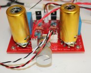
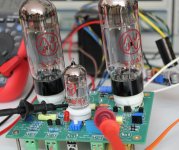
You just need to connect the screen output 2 to plate output 1 as well as 4 to 5 for the triode mode, or both screen output 2 and 4 to high voltage output 3 for the pentode mode, please refer to the pictures and see the yellow wires !
It is very simple and you can test the different wiring yourself to find what you prefer, you can even add a switch to select triode / pentode when your amplifier is in a chassis. Personalty I will stay with the UL mode if you have an output transformer with UL wires, but I have found both the pentode and the triode mode very good too, people say that triode mode is better at the price of a lower output power ?
May be the special feedback of the Baby Huey reduce the differences between these different architectures ? I know that Yves M use only pentode output, but he is using global feedback... Many possibility can be tested with this small board 😀
Have a nice testing week-end,
Marc
You don't need to add an other resistor, they are already on the boart : R14 & R15, 270 ohms 2 W 🙂
You just need to connect the screen output 2 to plate output 1 as well as 4 to 5 for the triode mode, or both screen output 2 and 4 to high voltage output 3 for the pentode mode, please refer to the pictures and see the yellow wires !
It is very simple and you can test the different wiring yourself to find what you prefer, you can even add a switch to select triode / pentode when your amplifier is in a chassis. Personalty I will stay with the UL mode if you have an output transformer with UL wires, but I have found both the pentode and the triode mode very good too, people say that triode mode is better at the price of a lower output power ?
May be the special feedback of the Baby Huey reduce the differences between these different architectures ? I know that Yves M use only pentode output, but he is using global feedback... Many possibility can be tested with this small board 😀
Have a nice testing week-end,
Marc
What is the gain of this amp? So the 12ax7 ltp won't exceed 50x and is probably about 30x or so. And the output might be as much as 4x with the el34's.
How much feedback db is the schade-type feedback arrangement?
Has this been posted or measured? Just curious. And wondering how much nfb can possibly be employed without having enough gain for a typical source such as a cd player or sound card.
How much feedback db is the schade-type feedback arrangement?
Has this been posted or measured? Just curious. And wondering how much nfb can possibly be employed without having enough gain for a typical source such as a cd player or sound card.
Last edited:
Hi Tom,
I think I would be more concerned about stability with more feedback. This might be the limiting factor.
-Chris
I think I would be more concerned about stability with more feedback. This might be the limiting factor.
-Chris
I am confused?
Hello again:
I have been slowly working on my BH project and seem to be at a place where I do not know what to do.
I have stuffed the boards and got the power supplies sorted out. The heaters power up properly.
I am trying to adjust the bias and that is the problem. I installed a set of older 6v6 tubes to do the testing.
My bias reads 450ma on one output tube and 860ma on the other. The trim pot does not change anything.
Could some one familiar with the board check my work and provide me with some guidance.

thanks for the help
Hello again:
I have been slowly working on my BH project and seem to be at a place where I do not know what to do.
I have stuffed the boards and got the power supplies sorted out. The heaters power up properly.
I am trying to adjust the bias and that is the problem. I installed a set of older 6v6 tubes to do the testing.
My bias reads 450ma on one output tube and 860ma on the other. The trim pot does not change anything.
Could some one familiar with the board check my work and provide me with some guidance.
thanks for the help
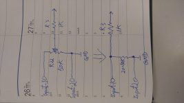
Hi Scott,
May be your problem of bias is caused by the value of R39, as explained in my post 2078, this value is too high for 50 V AC or less, I suggested to use 18 k or even 15 k instead of 33 k as you have on your picture 😱
To avoid this problem for future builders, I have added an updated BOM in this post 🙂
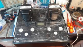
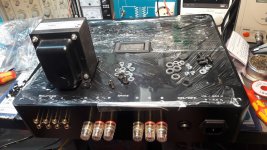
My EL34 Baby Huey will have its home soon, thanks to my friend Philippe that is doing the hard mechanical work that I am not able to do myself 😉 The top cover has been made by Front Panel Express, expensive but very good quality, the front and rear panels are made by Philippe, here are two pictures of the work, next step the front panel with two vu-meters !
Will keep you updated,
Rgds,
Marc
May be your problem of bias is caused by the value of R39, as explained in my post 2078, this value is too high for 50 V AC or less, I suggested to use 18 k or even 15 k instead of 33 k as you have on your picture 😱
To avoid this problem for future builders, I have added an updated BOM in this post 🙂
My EL34 Baby Huey will have its home soon, thanks to my friend Philippe that is doing the hard mechanical work that I am not able to do myself 😉 The top cover has been made by Front Panel Express, expensive but very good quality, the front and rear panels are made by Philippe, here are two pictures of the work, next step the front panel with two vu-meters !
Will keep you updated,
Rgds,
Marc
Attachments
- Home
- Amplifiers
- Tubes / Valves
- EL84 Amp - Baby Huey