Note that the choice of transistors isn't critical- the lower one can be any small NPN with reasonably high hfe. The upper one needs to be able to handle more voltage and power, so an MJE340, TIP50, or anything like that can be used.
CCS and all that sand!
Would it be possible to balance the LTP by connecting a 1k-5k pot between the cathodes, then connecting the wiper to the tail resistor? And then maybe changing the tail resistor from 18k to 15k? The bad part would be in measuring the AC balance every time you rolled in a different tube. I don't know fer sure but would the imbalance between tube sections would be that great to cause concern? As you know EICO and others have manufactured these (LTP) amps without AC balance adjustments, and are we just being anal?
But yes I agree, to address our concerns a CCS would be the way to go, which would assure (almost) perfect AC balance and would not be hard to implement save for the -B supply if implemented. The CCS Jojo posted looks to be very easy to construct that is if you don't mind standing your 6SN7 on all that sand! 😉
If you have an old VCR laying around you would most likely have all the parts needed to construct Jojo's CCS!
I am going to add this to the circuit I've posted (#206) and do a simulation and post the resulting schematic along with the transient and AC gain results when I get home to-nite.
I don't know how I missed Jojo's CCS but I'm glad he posted it again for our education.
Thanks to everyone and navin for their emotional support! And I always come here for an up-lift in my day! 😉
Wayne
P.S. navin, coming here and thinking about toobes and such gives me a 'little' vacation from reality! 😎
Frankly, I can see no reason for not using a CCS with an LTP splitter. It removes completely the issue of AC imbalance and helps, or so they say, to give better transient response. DC imbalance is still a potential issue unless you use a well-balanced doubled triode (e.g. 6SU7) but the problem can be minimized by placing (unbypassed) resistors of, say, 1k in the cathodes.
how about BC546? I have a bunch of these.
Yeah, they look fine. "General purpose NPN" is a nice descriptor to look for.
As you know EICO and others have manufactured these (LTP) amps without AC balance adjustments, and are we just being anal?As you know EICO and others have manufactured these (LTP) amps without AC balance adjustments, and are we just being anal?
Yeah, probably. 😉
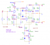
OK, now let's get anal. Here's JojoD818's CCS in the TAIL of the 6SN7 LTP I posted earlier. I did it quick and dirty using a MPSA42 HV transistor. As a safety margin we need one that can dissipate at least several watts, as we are statically dissipating 716mW.
This CCS can be built on a little PC board or perf board.
Wayne 🙂
Edit: I used a 3.3V zener because I didn't have a good red LED model, yet.
This CCS can be built on a little PC board or perf board.
Wayne 🙂
Edit: I used a 3.3V zener because I didn't have a good red LED model, yet.
Attachments
SY said:Agreed 100% on the balancing stuff. That's why I've given up, gone to the Dark Side, and use a solid state CCS in the cathode.
I will also "confess my sins" and mention that in a recent 2 x 100W tube amplifier (high-end), I used 28 transistors and 3 ICs, albeit all in power control and safety sensing circuitry. The 2 amplifiers themselves use only 13 tubes! There was no way I could have done this with all-tubes. I have perhaps my "dedication" to nostalgia more than many others younger than me, having been brought up in that era, but I am also a humble EE, and I will be hanged before I sacrifice integrity and be un-optimal as an engineer. We use modern metal-film resistors, polyester and poly-carbonate capacitors, ceramic trimpots, have our chasses cut with computer-aided laser tech etc, so. (Just a pity those NOS tubes are drying up ....)
As for the other comments I will certainly oblige, but I am going to be out of contact for a few days.
Regards.
cogsncogs said:OK, now let's get anal. Here's JojoD818's CCS in the TAIL of the 6SN7 LTP I posted earlier. I did it quick and dirty using a MPSA42 HV transistor. As a safety margin we need one that can dissipate at least several watts, as we are statically dissipating 716mW.
This CCS can be built on a little PC board or perf board.
Wayne 🙂
Edit: I used a 3.3V zener because I didn't have a good red LED model, yet.
hi,
i would be more confident with a tip50, mje13005, mje13007, etc to-220 types in there as they can dissipate more.
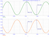
btw, may i know the max output of the differential stage in pk 2 pk values prior to clipping?
thaks a lot.
Johan Potgieter said:
I will also "confess my sins" and mention that in a recent 2 x 100W tube amplifier (high-end), I used 28 transistors and 3 ICs, albeit all in power control and safety sensing circuitry. The 2 amplifiers themselves use only 13 tubes! There was no way I could have done this with all-tubes. I have perhaps my "dedication" to nostalgia more than many others younger than me, having been brought up in that era, but I am also a humble EE, and I will be hanged before I sacrifice integrity and be un-optimal as an engineer. We use modern metal-film resistors, polyester and poly-carbonate capacitors, ceramic trimpots, have our chasses cut with computer-aided laser tech etc, so. (Just a pity those NOS tubes are drying up ....)
As for the other comments I will certainly oblige, but I am going to be out of contact for a few days.
Regards.
this makes a lot of sense to me! techniques learned with solid state amps can be apllied beneficially to tubes.
i am also looking at a diffferential amp to make biasing the output tubes easy just looking at led displays.
I like the idea of using LED's . They are much quieter than zeners and plus they will give you a visual indication that the circuit is 'fired up'. You can also use a series string of diodes in place of the LED's. I'm leaning towards using a CCS in my own driver stage mod/upgrade of my VAL VAA-70Mk II PP UL amp. By the time I get done it will not be the same amp! I have boxes of bagged up Bi-polar and JFET/MOSFET transistors I have collected over the years, so I might as well use them.
The pros, almost perfect AC balance and a much improved common mode rejection ratio. Plus you won't have to use tons of NFB to things into ...
Transient Anylasis at the onset of clipping, more than enough drive for an EL34 PP pair:
Cheers
Wayne
The pros, almost perfect AC balance and a much improved common mode rejection ratio. Plus you won't have to use tons of NFB to
things into ...btw, may i know the max output of the differential stage in pk 2 pk values prior to clipping?
Transient Anylasis at the onset of clipping, more than enough drive for an EL34 PP pair:
Cheers
Wayne
Attachments
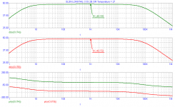
And here the AC analysis from 1Hz to 1MHz:
Wayne
Edit: using a lower value 6SL7 anode resistor will give a wider bandwidth. But remember to keep to anode voltage around 110-115V or so, which means either adjusting the cathode resistor or the supply voltage for the 6SL7.
Wayne
Edit: using a lower value 6SL7 anode resistor will give a wider bandwidth. But remember to keep to anode voltage around 110-115V or so, which means either adjusting the cathode resistor or the supply voltage for the 6SL7.
Attachments
Hi Group:
I've been following this thread using the CCS source.
It's been very informative and useful. I have one question though.
Is the main idea here to acheive better balance. I've built the
circuit with a 20K tail resistor and the CCS shown. My measurements say that the AC balance between both halves of the 6SN7 is identical with the CCS. The band width is also a little wider. I'm I on the same page? Also are there any advantages using a negetive supply on the tail with a CCS?
Any input apprecaited.
RonL
Hi Ron,
The idea is an almost perfect balance, especially when (for the circuit in question over the last posts) the 2 triodes in a tube can differ - and unfortunately they sometimes do by as much as 20%. Equal output amplitudes can be achieved by adjustment in anode load resistors with only a common cathode resistor, and this was the simple route followed in the past. But modern semiconductors are so convenient (I would almost say alluring) that one can hardly not use that alternative.
Depending on your background, you would realise that the "mechanism", say with a fully balanced stage (not phase inverter), is that any anode current signal on tube 1 bigger than on tube 2, would immediately reflect on the common cathode load (which is infinite in the case of a CCS) as a grid in-phase signal for tube 1 and out-of-phase signal for tube 2, such that equality in anode current is forced. For the Schmitt phase inverter there is always signal on the cathode but the equalising mechanism is the same.
A negative supply for the CCS is not always necessary. It will depend on the maximum signal which needs to be handled at any stage. Good transistor CCSs can still work with only a few volt over them, but one naturally needs to be sure that the maximum signal to be handled falls within its linear region. In the case of the Schmitt - often direct coupled to a previous stage anode - one does not have a problem with minimum voltage. H.f. balance will of course also depend on the bandwidth of the CCS. Since it is almost infinite impedance capacitances will influence it. (That can either be simulated if one has the necessary software, or experimentally with a small capacitor, signal generator and scope.)
It must be added for completeness sake that anode CURRENT balance is achieved. Should the load impedances differ or go unequal (e.g. because of output valve loading), voltage signal equality will no longer exist.
Wayne, SY,
from what I understand is the one reason why EICO and co did not used SS in the CCS is the fact that SS was not stable and prevaltent at the time their amps were designed and popular.
I for one dont care if it is SS or tube, Class A or Class D. If it sounds right it's fine. I visited my brother in law in singapore and he uses an Ella Consonance with EL34 tubes for the output and the sound was nice. Then he switched to 6550 (he also changed teh driver tube) and wow there was a significant improvement. I wont say the amp was more transparent or anything like that but it sounded much more like music.
One reason I am leaning towards the 6SL7-6SN7 ckt Wayne posted is that once the EL34 amp is done I do intend to get a set of 6550 and try them out. the 6SL7/6SN7 should have no touble with the 6550 I hear. Maybe I'd need to change the biasing on the power tube.
Wayne, if and when you get the time (I am in no hurry) can you post a ckt for the EL34 power section? I dont have any tube skills so I fear I will damage my tubes if I try something on my own.
Thanks Johan:
This is what I've thought about CCS. I just needed to hear
someone else say it. I'm building a similar design but using
12AT7 LTP and KT88's in UL.
Thanks for the reply!
RonL
This is what I've thought about CCS. I just needed to hear
someone else say it. I'm building a similar design but using
12AT7 LTP and KT88's in UL.
Thanks for the reply!
RonL
Seeing that I am gonna end up with a 6SL7, 6SN7 and EL34 amp has anyone studied this schematic. Wayne? SY? Anyone? Can it be used in UL too?
http://audiotropic.netfirms.com/Projects/ampEL34.html
the other schematics are in post 8 and 10 earlier on this thread.
incl. one that used 2 ECC88 per channel (alled PP-1C).
http://audiotropic.netfirms.com/Projects/ampEL34.html
the other schematics are in post 8 and 10 earlier on this thread.
incl. one that used 2 ECC88 per channel (alled PP-1C).
I don't understand why this designer took the trouble and complication to turn the first stage into an SRPP (a plain-vanilla grounded cathode stage works fine here) but didn't take care of the phase splitter's fundamental problems. And by going to triode, the stability is possibly compromised because of the new, nasty poles from the output stage's Miller effect.
I agree with SY's comments.
A far better solution, IMHO and IME, is to use the 6SL7 as an input LTP splitter (with pentode CCS in my case) and to follow that with 6SN7 differential driver. This has the added advantage of being immune to PS hum, which an SRPP front end is not. If you're interested, I have posted my schematic in at least ine other thread on this forum but I can't remember which one.
A far better solution, IMHO and IME, is to use the 6SL7 as an input LTP splitter (with pentode CCS in my case) and to follow that with 6SN7 differential driver. This has the added advantage of being immune to PS hum, which an SRPP front end is not. If you're interested, I have posted my schematic in at least ine other thread on this forum but I can't remember which one.
ray_moth said:If you're interested, I have posted my schematic in at least ine other thread on this forum but I can't remember which one.
of course i am interested. but where would i find this schematic?
re: wayne's circuit
i noticed that gain is quoted as 48db, assuming a closed loop gain of 20db, so feedback is 28db.
are these values costumary for tube amps? i know ss amps have more open loop gain than 48db, so what if we lower that to say 36db, what are the consequenses if we do this?
i also noted that quiscient plate dissipations are way below plate ratings for either tubes, can you give more insights into this? i read somewhere that 25% plate rating is limit for signal tubes.
thanks
tony
- Status
- Not open for further replies.
- Home
- Amplifiers
- Tubes / Valves
- EL34 schematic confusion