navin said:BTW JoJoD what preamp are you using?
i have a 12au7 preamp, a version of Frank's 5692/6SN7 preamp and a 12SN7 preamp. The 6SN7 is in the process of having a new chassis while the 12SN7 is planned to be renewed with a pair of 6201 ala JB's Aikido. all of which are linestages since I use cdp as source. and finally, I'm still dreaming of building SY's heretical preamp.
how about you, what preamp do you use navin?
🙂
JojoD818 said:
how about you, what preamp do you use navin?
I use SS. the EL34 tube amp is my first.
Presently my preamp is a home made one using relay swtiching and a OP275 for buffer. the power amp uses 3 pairs of Hitachi SJ50/SK135 MOSFETs and a 1200VA tranny. it puts out about 200W/8ohms. My crossover is passive. All this was built 10+ years ago.
Now we intend to shift house (sometime 2006) and i figured it was time to rebuild the old system. My needs have changed (I dont need 4 12" subs or 200W+ anymore).
So I figured I'd use the subs for a seperate HT system (mated to a yet to be decided fullrange driver like the Jordan JX92 or J6), rebuild the speakers (into a push push 2 way) and power them with tubes.
since i only have a CD player and Ipod as sources I intend to use just a passive 50K volume control and input selector mated to Steve bench's ECC88 Crossover mated to the EL34 power amps discussed on this thread.
beyond the EL34 amp I am thinking of a EL84 PP Triode amp as well. Just that I want to tackle one project at a time. The EL84 amp would also require a small but sensitive fullrange speaker (Fostex 103/108 or FX120). Any ideas for the EL84 schematic?
Originally posted by: SY
It may well be, but the specimens of the GE 5 Stars I've tested show a very poor harmonic distribution, with the 5th being nearly double the percentage of the 3rd.
Well thanks to SY and his harmonic distortion measurements! They should be the same except for the mounting. May be caused by a different plate structure i.e. size and shape of the plate. As we all know the 12AT7 comes in different sizes and shapes.
I'm really enjoying this thread. Let's keep the ideas coming. I will try to get that diagram posted here in few minutes.
JojoD818, nice layout!
Off topic:
navin this is third tumor in the past 4 years. We are hoping that by taking radiation therapy again (if she can take the full 3-4 weeks of treatment, as she is pretty weak and surgery is not an option) that it will go in remission for a few years. As far as curing it, we don't think it will, but will add, you know, a few more years to her life.
I'll be back!
Wayne 😎
Wayne, sorry to hear about this. There have been so many advances in the past ten years; I hope that you can enjoy more time with her.
On less important matters, I think the biggest cause of variability in distortion between 12AT7s is the accuracy of grid winding.
And after seeing Jojo's work, I'm permanently giving up building amplifiers.
On less important matters, I think the biggest cause of variability in distortion between 12AT7s is the accuracy of grid winding.
And after seeing Jojo's work, I'm permanently giving up building amplifiers.
Originally posted by: SY
On less important matters, I think the biggest cause of variability in distortion between 12AT7s is the accuracy of grid winding.
Haven't thought of that. So wouldn't that vary between tubes of the same type or would that be pretty consistent? The spacing of the grid wires, closer together in the middle and further apart at the ends, not quite to the extent but like a variable mu (semi-remote cutoff) triodes such as a 6ES8, 6ER5, 6ES5? Maybe it was intended this way so as to give the 6201 a little more headroom as this tube was designed as HF amplifier/oscillator/mixer. Just a thought.
And after seeing Jojo's work, I'm permanently giving up building amplifiers.
Just take your time. My work usually starts out that way but after making adjustments...
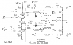
OK navin, as promised here's a 6SL7 going into a 6SN7 LTP. Now this model for the 6SL7 doesn't model grid current. I would keep the 150k or 120k anode resistor and adjust the cathode bias resistor(s) and/or the plate supply voltage to get around 110-115V on the plate of the 6SL7. R13 (36k) and C6 (82p) form a RC phase lag HF compensation network. This may or may not be needed in your amplifier. This network can also be placed in // with the 150k plate resistor. Also the values of the grid stoppers are not set in stone and may not be needed at all. This will be determined by your OPT and layout. So when you begin to build your amp(s) you will have to tweek these values and not to mention your NFB loop. This is how it's done.
Now if we had the same OPT's (if we were building the same amp) and other components I could give you the values and all would be well. And plus you are having your iron custom wound/made. I hope you have a scope, you may very well need one. Also hopefully when you recieve your OPT's they are closely matched

I don't find this tweeking or fudging a problem, it adds to the fun of building your own amplifier!! 😀
R4 (27k) and R5 (30k) should be 2W types. All others 1 watt except the 18k tail resistor which is a 3 watt. I wouldn't use an inductive WW 18k tail resistor. I've found the metal oxide resistors work great. You could use 1% metal films for the 6SL7 and the 100k grid leaks. This is important for the grid leaks for the output stage as you want them well matched. You may already know this but I'm also writing this for others who kmay be watching this thread and are hiding in the shadows
 😉
😉 And also stand each EL34 on 10R 2W resistors to aid in measuring bias current, even if you are using cathode/self-bias. As an added benefit they will add a little degenerative feedback into the output stage. And again don't use inductive WW types here also. I've found that doing so caused HF stability problems, at least in my amplifier.
Wayne
navin,
I started with a lot of SS too, discretes and chip amps and still love them. Though tubes takes a lot of my time now.
😀
I started with a lot of SS too, discretes and chip amps and still love them. Though tubes takes a lot of my time now.
😀
cogsncogs said:
JojoD818, nice layout!
Off topic:
navin this is third tumor in the past 4 years. We are hoping that by taking radiation therapy again (if she can take the full 3-4 weeks of treatment, as she is pretty weak and surgery is not an option) that it will go in remission for a few years. As far as curing it, we don't think it will, but will add, you know, a few more years to her life.
I'll be back!
Wayne 😎
Thanks! But with the new ideas coming in I don't think I can maintain order inside my amp. 😀
Sorry to hear this too Wayne.
SY said:
And after seeing Jojo's work, I'm permanently giving up building amplifiers.
I sure hope you approve of my layout. 😀
This is my fixed bias Williamson in EL34. 🙂
cogsncogs said:
navin this is third tumor in the past 4 years....she is pretty weak and surgery is not an option) that it will go in remission for a few years. ...a few more years to her life.
Wayne 😎
Wayne. We are praying. My son, wife and I. We Indians are big on prayer and faith.
cogsncogs said:oopps forgot the diagram, here it is!
Geez. Wayne. I am soooo obliged. If I were in your boat I dont think I would have been able to conjure this. Spend time with your mom. Tube amps can wait.
Just a brief practical observation re Wayne's circuit (post #206) - not trying to be judgmental:
This is (almost) the same circuit I became fond of over the years, but I sadly found myself beleaguered by tube tolerances. Even halves of the same double triode were sometimes so different that I had to install a small trimpot between the anode loads of 27K and 30K to get balance in the output stage. About 5K, and I am sure it could just be added without making too much of shift in anode voltages (or just a 5K + 27K in the lower limb). Or if the amplifier will remain your own, perhaps more elegant to check each time you replace a 6SN7 and adjust the load resistors. But be sensitive to the possible unbalance.
This is (almost) the same circuit I became fond of over the years, but I sadly found myself beleaguered by tube tolerances. Even halves of the same double triode were sometimes so different that I had to install a small trimpot between the anode loads of 27K and 30K to get balance in the output stage. About 5K, and I am sure it could just be added without making too much of shift in anode voltages (or just a 5K + 27K in the lower limb). Or if the amplifier will remain your own, perhaps more elegant to check each time you replace a 6SN7 and adjust the load resistors. But be sensitive to the possible unbalance.
SY said:Johan, even with the pole outside of the feedback loop, you'd expect that, no? Or did you actually see stability change, not just rolloff?
Correct SY, but as I recall it was a change in ringing (on square wave) which I could correct with the lead cap over the feedback resistor. But let me check some time as said. I have a chassis here fitted with sockets and tagstrips etc. for such adventures. Perhaps followed by a set of data to illustrate typical behaviour for the interest of those - er, well, who are interested! Give a week or so.
Thanks, Johan, that would be extremely interesting!
Of course, you could even expect some ringing changes with the pole external; the total transfer function will be the product of the transfer function of the external pole (first order, 0.707) with the transfer function of the amp (if there's ringing, it will be high Q). With some clever juggling, you could make the first partially compensate the second to flatten out the overall response, but I sure wouldn't want to count on the long term stability of this solution!
Agreed 100% on the balancing stuff. That's why I've given up, gone to the Dark Side, and use a solid state CCS in the cathode.
Johan Potgieter said:..Even halves of the same double triode were sometimes so different that I had to install a small trimpot between the anode loads of 27K and 30K to get balance in the output stage. About 5K, and I am sure it could just be added without making too much of shift in anode voltages (or just a 5K + 27K in the lower limb).
can this be done without use a pot in the signal path?
Sure, make both plate resistors the higher value, then use a large parallel resistor to trim the gridfed side. The fiddling will be tedious if you want to adjust things (this is at high voltage, so patience or creativity will be needed to change trim resistors safely), but it can be done.
Again, a cathode current source is simple, cheap, works well, and automatically balances that stage...
Again, a cathode current source is simple, cheap, works well, and automatically balances that stage...
SY said:Again, a cathode current source is simple, cheap, works well, and automatically balances that stage...
"simple and works well" magic words. How does one implement this on the ckt in post 206. does one have to have some sort of SS curent mirror ckt where R3 18k is?
"simple and works well" magic words. How does one implement this on the ckt in post 206. does one have to have some sort of SS curent mirror ckt where R3 18k is?
yes a ccs with 6.83mA, a tip50 transistor can be used here.
What happens to R4 and R5 then. Are they both 27K or are they 27 and 30K.
yes, same value. which value, your pick.
navin said:
"simple and works well" magic words. How does one implement this on the ckt in post 206. does one have to have some sort of SS curent mirror ckt where R3 18k is?
we already have a solution for that, don't you remember? the ckt came from SY and I posted a redrawn version already. 😉
with the ccs, we use the same 33k resistor for the upper and lower limbs of the phase inverter.
- Status
- Not open for further replies.
- Home
- Amplifiers
- Tubes / Valves
- EL34 schematic confusion