Navin and others,
I think you will be pushing things a bit by simply using 12AX7 (same as 7025) or 6SL7 or ECC88 with out more ado. They are quite dissimilar. The Mu's are for ECC83 = 100, for 6SL7 = 70 and for ECC88 = 28. Apart from that the bias differs for the same anode current (which presumably must stay reasonably similar so as to maintain the designed anode voltages). E.g. for the same conditions ECC83 will need -1.2V bias, compared to 6SL7 of -2.7V. The ECC88 again is much less sharp cut-off. Yes, they will work in that the amplifier will probably produce music, but hopefully we are talking here about getting lowest distortion, ergo optimal operating points or close to. For that bias adjustment would be required. There is a reason ( or should be) why a designer has decided on a certain anode operating point.
Then I apologise to regular readers for boring repetition, but an ECC83 is not the best input triode if the input volume control is 500K as shown or more, because of total grid capacitance. Your h.f. response will be affected by the control position, either audibly so or by influencing feedback characteristics. If you must use a triode as input stage, I would not go to a higher mu than 30-ish (i.e. ECC88). If that cannot give sufficient gain, pentode or cascode is your route.
As for serie G2 resistors, Mullard characteristics for the EL34 show decreased distortion with 1Ks in serie (that is for UL), which is recommended by them. Beam tubes (6L6, 7027, etc.) are not so sensitive. In triode mode it is the custom to insert 100 ohm screen resistors, but I have never been convinced that this is not a largely pious fashion. (OK, I put them in too.) Has anybody ever encountered difficulty without them? Still, resistors are cheap enough.....
Regards.
how about, the engineers chickened out last minute! fixed bias give more power but maintenance wise, once something goes wrong with the bias pots, the output tubes could be lost.
Take a look at the schematic I posted here:
www.diyaudio.com/forums/showthread.php?s=&threadid=40609&perpage=10&highlight=&pagenumber=3
If something goes wrong with the bias adjustment pots, say the wiper loses contact with the track, the 30k resistor kicks in and applies the nearly full bias supply voltage to the grid of the EL34. Neat huh? 😉
As far as which tube to use in the first hole:
12AX7A/ECC83/7025 = too much miiler capacitance, but high gain.
12AT7/ECC81 = Good choice. Strident? Not at all IMHO, maybe just good HF response...
6DJ8/ECC88/6922 = Ok choice, not the best. 6922 better of the three, higher permissable plate voltage.
12AU7 = Naaahhh! As Sy stated.
6SL7 = Good...
5751 = Same boat as ECC81
6N2 = good swing. Really isn't the same as a ECC88.
6SN7 = Too much of a good thing.
12BY7 = Very nice, pentode or triode connected.
Lots of other tubes that may not be availible where navin resides.
My choice would be 6SL7, 12AT7, 6N2, or a 12BY7

Cheers ya'll
Wayne :B 😀
Johan Potgieter said:
...The Mu's are for ECC83 = 100, for 6SL7 = 70 and for ECC88 = 28.... I apologise to regular readers for boring repetition, but an ECC83 is not the best input triode..If you must use a triode as input stage, I would not go to a higher mu than 30-ish (i.e. ECC88). If that cannot give sufficient gain, pentode or cascode is your route.
As for serie G2 resistors, Mullard characteristics for the EL34 show decreased distortion with 1Ks in serie (that is for UL), which is recommended by them. ..In triode mode it is the custom to insert 100 ohm screen resistors, but I have never been convinced that this is not a largely pious fashion. (OK, I put them in too.) Has anybody ever encountered difficulty without them? Still, resistors are cheap enough.....
1. given todays sources a Mu of 30 should be enough. If not the 6SL7 will definitely be adequate.
2. A pentode input is more often recommended but with a smaller volume pot (say 50K) I'm told a triode like the 1/2 ECC88 / 6922 or 1/2 6SL7 will do ok.
cogsncogs ,
very clever circuit trick, thanks a lot.
i have japanese 12by7's ever tried them? how about 6cl6?
thanks.
very clever circuit trick, thanks a lot.
i have japanese 12by7's ever tried them? how about 6cl6?
thanks.
cogsncogs said:
...6DJ8/ECC88/6922 = Ok choice, not the best. 6922 better of the three, higher permissable plate voltage.
6SL7 = Good...
12BY7 = Very nice, pentode or triode connected.
My choice would be 6SL7, 12AT7, 6N2, or a 12BY7
Funny. Where I reside the ECC81 and ECC83 are available but not easily. However I am being gifted a pair of 6SL7 (NOS unused Russion tubes) till I get my own later.
I now need to find 2 octal tube sockets. believe me doing this in India is agravating. No wonder everyone I know bought those HTiB systems!
One other good first hole candidate would be triode-connected EF86, should such be available out your way.
SY said:One other good first hole candidate would be triode-connected EF86, should such be available out your way.
before i get side tracked i think what i am probably going to start with is build the ckt posted by JoJoD818 using 1/2 6SL6, 6SL7 and 2 EL34 in UL.
Does anyone have any serious issues with this ckt. JoJoD818 uses a 7025 which is not the same as 6SL6 and I really would like to know if there are any changes required to accomodate teh 6SL6 instead.
1. given todays sources a Mu of 30 should be enough. If not the 6SL7 will definitely be adequate.
Ok, lets clear some smoke here. The mu of a tube is the theoretical (max) gain of a tube/triode. The actual gain will be determined by the circuit values chosen. A good choice of gain for the entire AF Amp-1st stage / Phase Splitter would be around 40-45db, that is BEFORE NFB is applied. 775mV to 1V input sensitivity would be what to aim for. In a 30-50W PP-UL amp I don't see an advantage of going no feedback IMO. The less NFB you can get away with the better of course. Nested feedback is one choice, sometimes along with global FB and/or cathode windings in the OPT. Using good iron, the less NFB you will need and at the same time the more NFB you can apply without creating an oscillator. But using tons of NFB to tame a circuit is always bad, SS comes to mind here, hehe.

Tony, A 12BY7 was used as a wideband video amplifier (TV toob!) and makes an excellent AF amplifier as well. I haven't used one in a long while and yes they were Japanese. And believe it or not they did make some very good toobs. IIRC I had no complaints! Also used them in rebuilding/moding an old 1 or 2MHz EICO 'silly-scope. I've never used a 6CL6 power pentode as a voltage amp, so I can't comment.
Wayne :=B
cogsncogs said:
Ok, lets clear some smoke here. The mu of a tube is the theoretical (max) gain of a tube/triode. ..The less NFB you can get away with the better of course...Using good iron, the less NFB you will need and at the same time the more NFB you can apply without creating an oscillator....
thanks but is the 6SL7 a drop in replacement for the 7025?
BTW Imade 2 typos earlier the ckt I was thinking of using is JoJoD's ckt using 1/2 7025, 6SN7 and EL34 but replacing the 7025 with 1/2 6SL7 instead.
thanks but is the 6SL7 a drop in replacement for the 7025?
A 7025 is a low-noise version of a 12AX7. Yes and no. Depending, little or no changes in circuit values will be required. In JoJoD's circuit you may need to alter the cathode or anode resistors to get somewhere around 110-120V on the plate of the 6SL7. This is somewhat critical as the plate of the 1st stage is direct coupled to the grids of the 6SN7, which determines the operating point of the 6SN7 LTP. And you want this (ideally) to place the LTP near it's most linear operating point (distortion) as possible to get maximum voltage swing with clipping occurring in a symmetrical fashion.
Cheers
Wayne
cogsncogs said:may need to alter the cathode or anode resistors to get somewhere around 110-120V on the plate of the 6SL7.
maybe i can use a 1K, 100K pots on the cathode and anode respectively and adjut till i get 110V on the plate of the 6SL7 right?
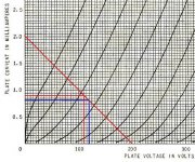
jane said:With Ra=100k and B+=200V, you will have 110V on the plate with a 1.38k cathode resistor (red curve) and 120V on the plate with a 1.74k cathode resistor (blue curve).
The resistors should of course be:
Plate 110V: R=Ug/Ia = 1.1V/0.9mA = 1.2k
Plate 120V: R=Ug/Ia = 1.25V/0.8mA = 1.6k
Sorry for my miscalculations in the first place

wayne,
very nice circuit mod for the bias circuit, better safe than sorry! 😀
navin and others,
it was adviced by SY that if I use a 50K-100K pot that the 7025's grid capacitance would be ok.
the circuit I posted still has some typos in it but I will post a new revised circuit with all the corrections and modifications we have discussed. however the tube compliments would still be 1/2 7025, 6SN7GTB, and EL34 since that is what I would like to try.
as for the screen resistor, I ended up using 1K per opt tube. but the switch is still there. 😉
Plate 110V: R=Ug/Ia = 1.1V/0.9mA = 1.2k
Plate 120V: R=Ug/Ia = 1.25V/0.8mA = 1.6k
I see jane whipped out the plate curves! Sorry I was too lazy to do it myself. 😀 Now this is with a bogey 6SL7, so in real life...it will get you in the ball park! Toob parameters don't vary much between toobs unlike JFET's.
navin, no need to go with variable pots, just tack the parts in. Build the driver section first before building the EL34 output section. Use a 1k-1.2k or so cathode bias resistor and vary the feedback shunt resistor. I've found that a 6SL7 'likes' a 120k-150k anode resistor, 44,000 Rp x 3 = 120k. Also a B+ of 420V may not be needed for the 6SN7 LTP, maybe try 390V or so, so as to have a higher dropping/divider resistor to help with better PS decoupling. Of course the maximum voltage swing will be lower but you don't really need that large of a swing as we are driving an EL34. And... if you use an CCS in the tail, even better but not necessary. Always try the simpler route first. But if you got it in you hey don't let me stop you! 😀
And don't forget the protection diodes on the grids of the 6SN7 LTP. I've always wondered though about the effect of the reversed bias junction capacitance of the diodes as per to driving the little voltage dependant caps of the diodes. Shouldn't be of any consequence. That's how tuning diodes work. I think the advantage of doing so outweighs the cons.
When I get back to-nite from the hospital I will post a 6SL7/6SN7 Amp/LTP.
Off topic, my Mother has throat cancer, that's why I've been away for a while.
Originally posted by: JojoD818
I have a bunch of 6201 which I also plan to be used in lieu of the 7025.
Very good! A special 5 Star military version of 12AT7/ECC81. But I still like a 12AZ7 better. Also a 12DT8/6DT8 as it has a shield between the two sections connected to pin 9. 5965A's are gaining in popularity. The used to be a dime a dozen.
it was adviced by SY that if I use a 50K-100K pot that the 7025's grid capacitance would be ok.
He is correct. I don't think by using those values, grid capacitance will be much of an issue. Using a 500k volume control it will be. I've seen some manufactuers compensate/patch (yukk) by using a small value compensation cathode bypass caps.
Wayne 😉
Very good! A special 5 Star military version of 12AT7/ECC81.
It may well be, but the specimens of the GE 5 Stars I've tested show a very poor harmonic distribution, with the 5th being nearly double the percentage of the 3rd.
jane said:
Plate 110V: R=Ug/Ia = 1.1V/0.9mA = 1.2k
Plate 120V: R=Ug/Ia = 1.25V/0.8mA = 1.6k
Sorry for my miscalculations in the first place
Thanks Jane. I think 1.5K is a standard resistor and given the 5% tolerance we can find 1.6K. BTW should I use metal film or carbon? Any advantage to using metal film?
JojoD818 said:
the circuit I posted still has some typos in it but I will post a new revised circuit with all the corrections and modifications we have discussed. however the tube compliments would still be 1/2 7025, 6SN7GTB, and EL34 since that is what I would like to try.
as for the screen resistor, I ended up using 1K per opt tube. but the switch is still there. 😉
Hey I am waiting for that ckt so I can make a bill of materials and start shopping. also when you do make that ckt please let me know the watt ratings on the resistors. 🙂
I'll be using a 6SL7 instead.
cogsncogs said:
navin, no need to go with variable pots, just tack the parts in. Build the driver section first before building the EL34 output section. Use a 1k-1.2k or so cathode bias resistor and vary the feedback shunt resistor. I've found that a 6SL7 'likes' a 120k-150k anode resistor, 44,000 Rp x 3 = 120k. Also a B+ of 420V may not be needed for the 6SN7 LTP, maybe try 390V or so, so as to have a higher dropping/divider resistor to help with better PS decoupling. Of course the maximum voltage swing will be lower but you don't really need that large of a swing as we are driving an EL34. And... if you use an CCS in the tail, even better but not necessary. Always try the simpler route first. But if you got it in you hey don't let me stop you! 😀
And don't forget the protection diodes on the grids of the 6SN7 LTP. I've always wondered though about the effect of the reversed bias junction capacitance of the diodes as per to driving the little voltage dependant caps of the diodes. Shouldn't be of any consequence. That's how tuning diodes work. I think the advantage of doing so outweighs the cons.
When I get back to-nite from the hospital I will post a 6SL7/6SN7 Amp/LTP.
Off topic, my Mother has throat cancer, that's why I've been away for a while.
Geez Wayne. I am very sorry to hear this. How bad is it? Is it curable? Thanks for all the help despite these difficult times.
As fo the rest of your post I'll have to print it and read it very slowly. No way I can understand at this speed. You see I am from a 3rd world country where we hang with cows and elephants and charm snakes for fun. 🙂
- Status
- Not open for further replies.
- Home
- Amplifiers
- Tubes / Valves
- EL34 schematic confusion