I think everything really depends on the specific needs, case by case: for me that multi-amp multi-speaker managing preamp would be way redundant, and a simple bluetooth module will be enough for tv+bluetooth in the living room and same for the phono+bluetooth in the attic.
Yep! That's the beauty of DIY, you can build the exact thing that meets your specific use-case.
I only have my turntable (phono pre) and a headless Daphile linux server through my dac connected. And I really don’t think that will change much over the years. Have had this setup for 10 years already.
And if I can keep the cases to a minimum the wife will be happier and it’s also easier to keep a clean look.
In this case a DAC with volume control and an analog input seems ideal as you'll stay with the same amount of cases.
Otherwise, the Mezmerize B1 buffer is a nice unit because it includes the inputs, volume pot and PSU in a single board and doesn't have gain.
If you run the EL84 in triode mode, there's no advantage in using the BH feedback.
Shunt a-g1 feedback triodizes the curves at the expenses of driver's current capability.
Running the tubes in pentode or UL, permit to have the g1=0 curve on the very left of the V-I plot, so to have more power than triode mode.
Joining the two you can have more power than triode, but still triode-like curves, just moved on the left of the V-I plot.
This way you find your own compromize between power, gain, distortion and Zout.
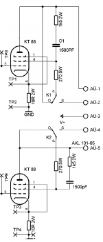
Hi all! I am trying to switch from pentode mode to triode mode with relays. See photos. I will write my experiences to you. Thanks to all B-H builders.
Tanks @zintolo
Attachments
I can't buy 10A rectifier with similar dimensions to KBU1004 in my country, the nearest one is 8A. Is it OK to use that one, if I add a heatsink to it?The ECC83 draws 0.3 amps so that's correct if you tested only one amp PCB? The El34's draw 1.5 amps each so your total heater current is around 6.6 amps for both PCB's.
Its a fair amount of current so you would expect them to be warm.
Have you got a temperature probe to check it? Ill do the same with mine and report back
- Twisted pairs can be simulated with PCB traces and vias, but I think that's a bit overkill and the current capacity of the vias would need to be checked.
- I plan to keep the heater runs as direct and short as possible, with signal carrying components / traces crossing at 90 degs etc etc.
- I may also use a humdinger pot in place of the artificial centertap to further cancel any noise - but Pete's board doesn't do this and I can't hear / measure much hum.
But basically, yes, up and over is possible and may be the only option once I do the calcs for trace width / clearance for 7.2A @ 6.3V...
[EDIT] that would be ~2.34mm trace width and 0.62mm clearance for a 2inch long trace at 7.2A, 10C temp rise with 2Oz copper.
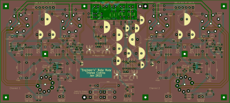
It's taken a while, but I've finally got somewhere with my "engineer's" BabyHuey. A single PCB for a stereo set-up with everything on it - much like Pete Millett's DCPP. Still some design rules to check (clearances around heaters and high voltage traces) and the mechanics (hole positions etc).
Would be keen to have another set of eyes check the layout. Attached is a recent render.
I'll post a final version and a link to Gerbers / KiCad source once it's finalised.
T
Attachments

This is a fantastic accomplishment! Well done. I am looking forward to the files to modify this for 6GM5 tubes.
May I give you two suggestions based on some time playing with that circuit?
Give the possibility to use a beefier bjt for the upper transistor of powerdrive's CCSs; install a trimmer to set the current of the phase splitter's CCS; give the possibility to install 500V power supply caps; split the voltages for phase splitter's negative rail, powerdrive negative rail (together with bias), powerdrive positive rail.
Give the possibility to use a beefier bjt for the upper transistor of powerdrive's CCSs; install a trimmer to set the current of the phase splitter's CCS; give the possibility to install 500V power supply caps; split the voltages for phase splitter's negative rail, powerdrive negative rail (together with bias), powerdrive positive rail.
I forgot one: give the possibility to install 200V power supply caps for the powerdrive negative rail.
If the amp is designed to work in AB2, or low gm tubes above 450V, can swing negative down to -2 to -3 times the negative bias voltage.
If the amp is designed to work in AB2, or low gm tubes above 450V, can swing negative down to -2 to -3 times the negative bias voltage.
What about making this open source?
After (hopefully) tristanc posts the files I was going to mod them for 6GM5 tubes. However, my take will probably be putting the amp on either separate left and right channel boards or both on one board. In either case I want the PS separate and will probably utilize one of the PS boards I've already ginned-up.
Frankly, I was thinking about starting this 6GM5 board design from scratch but waiting on tristanc's files as a head-start is too tempting to pass up. I'll post the 6GM5 board files here either for direct consumption or for someone else to take and further modify.
I have limited spare time right now and would eagerly start to modify tristanc's files if they were posted now as-is.
Thanks all.
Feel free to fork / adapt. I'm all for opensource / sharing etc and I'm keen (if this PCB works well) to have it stored somewhere like OSH Park, PCBway or Aisler where people can order their own board if they're interested: bypassing the group-buy hassle. I'd hope others would do likewise - including the KiCad source. I'll be getting either 3 or 5 boards made (depending on manufacturer min order qty) and one of those will wing its way to Australia for @gingertube .
@zintolo thanks for the suggestions. Can I clarify a couple of things, referring to the numbering in the PDF linked above:
I'm using various online calculators to calculate trace width and clearances. I can get away with 1oz copper it seems - the heater traces come out at 1.6mm assuming 3.3A per 'half' of the board, then dropping down to 0.5mm for the 0.3A runs. So I've rounded up a bit. Likewise for the HV traces - assuming ~0.2A at 400V gives tiny traces and 2.6mm clearance.
I'd really appreciate some voltage readings from a stock EL34 build - that way I could optimise some clearances and maybe trace widths. Will keep this thread / github updated.
Tristan
- My working repo is here: https://github.com/tristancollins/HiFi-BabyHuey
- The latest schematic is here: BabyHuey.pdf
- Latest render attached.
Feel free to fork / adapt. I'm all for opensource / sharing etc and I'm keen (if this PCB works well) to have it stored somewhere like OSH Park, PCBway or Aisler where people can order their own board if they're interested: bypassing the group-buy hassle. I'd hope others would do likewise - including the KiCad source. I'll be getting either 3 or 5 boards made (depending on manufacturer min order qty) and one of those will wing its way to Australia for @gingertube .
@zintolo thanks for the suggestions. Can I clarify a couple of things, referring to the numbering in the PDF linked above:
- Beefier BJT, is that Q306 / Q308 / Q406 / Q408? What would you suggest?
- Trim pot for driver CCS - that would replace R302 / R402? I had thought of that early on. A 1k would give enough range?
- What do you mean by splitting the voltage rails? I have each channel and feed isolated via a dropping resistor and cap. But haven't any isolation between the feed to the splitter and source follower CCS. "V_neg" in the schematic.
I'm using various online calculators to calculate trace width and clearances. I can get away with 1oz copper it seems - the heater traces come out at 1.6mm assuming 3.3A per 'half' of the board, then dropping down to 0.5mm for the 0.3A runs. So I've rounded up a bit. Likewise for the HV traces - assuming ~0.2A at 400V gives tiny traces and 2.6mm clearance.
I'd really appreciate some voltage readings from a stock EL34 build - that way I could optimise some clearances and maybe trace widths. Will keep this thread / github updated.
Tristan
Attachments
I downloaded KiCad and the Huey files. I know how to use DesignSpark so this will take some time to adapt to KiCad. I see no way to export KiCad to DesignSpark. It appears that KiCad is the eda of choice these days so its about time I learn it.
I've also got to learn some new words. E.g. what does "fork" mean?
I've also got to learn some new words. E.g. what does "fork" mean?
New ideas can be developed in different directions, with possibly different versions of the design as starting points. Github manages the creation of the new development as a fork, ongoing work is done on a branch, and then ultimately the branch (or multiple branches) can be merged back to the main branch. It enables people to develop ideas in parallel, without saving changes that could interfere with another persons idea.
@zintolo thanks for the suggestions. Can I clarify a couple of things, referring to the numbering in the PDF linked above:
- Beefier BJT, is that Q306 / Q308 / Q406 / Q408? What would you suggest?
- Trim pot for driver CCS - that would replace R302 / R402? I had thought of that early on. A 1k would give enough range?
- What do you mean by splitting the voltage rails? I have each channel and feed isolated via a dropping resistor and cap. But haven't any isolation between the feed to the splitter and source follower CCS. "V_neg" in the schematic.
As for the CCS, I suggest this old but still useful document: https://www.vintage-radio.net/forum/attachment.php?attachmentid=118321&d=1452609619
Only Q306 and Q307 are needed to be rated at higher voltage and wattage, Q301 is not needed if that CCS is supplied with -15V or so, that is what is needed to work properly.
Trimpot is instead (or in series with) R302, and 1kOhm is enough.
I mean give the possibility to have E.G. -120V for the driver, +50V for the driver and -20V for the phase inverter's CCS.
I'm just getting ready to place an order for 5 PCBs. I've made a few changes suggested, but tried to keep things simple where possible. My biggest concerns are around grounding and clearances of HV traces.
The top layer is a copper pour attached to signal ground, but there are a couple of 'islands' where I can see an issue - particularly around the source followers. But as they don't use much current I think it'll be OK.
As perfect is the enemy of good I'm intending on hitting 'submit' unless anyone sees any issues.
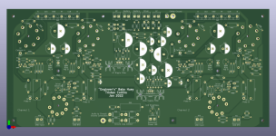
Latest layout is here: https://www.tristancollins.me/diyaudio/ibom.html
The top layer is a copper pour attached to signal ground, but there are a couple of 'islands' where I can see an issue - particularly around the source followers. But as they don't use much current I think it'll be OK.
As perfect is the enemy of good I'm intending on hitting 'submit' unless anyone sees any issues.
Latest layout is here: https://www.tristancollins.me/diyaudio/ibom.html
Looks great! What kind of sockets did you use for tubes? Ones with long legs, or normal ones?I got the chassis back from the paint shop on Friday. It was inexpensive and quick. The finish is a bit rougher than expected, but that's probably because this particular paint shop mainly deals with industrial stuff and machinery. Their main concern is corrosion protection and not so much about looks. I didn't think about that when I gave them the job. Still, it looks quite good.
Today I reinstalled all the parts, and took time to make the wiring tidy. Retested everything again, and it still seems to work (no smoke ...). Will hopefully listen to some music tomorrow.
This board looks cool, did you build it?hello guys,
I am noob with tubes so i don't have too much knowledge about this but somehow i designed my own PCB for baby huey amplifier 🙂 the winter is coming 🙂) Still remains to design a pcb for power supply and some delay for HV and after that i will send the gerbers to factory. And i need to continue to do more research about tubes amplifiers 🙂 This is first revision, still i need to do some optimization.
- Home
- Amplifiers
- Tubes / Valves
- EL34 Baby Huey Amplifier