Thanks! My adress Roman Pauliny RTVS Mlynská dolina 1 , 84545 BratislavaI have the old version of the pcbs with PSU onboard. I can sell.
I sent you 30Eur to your accountI have sent you the message.
Hi Ian, would you mind commenting this? I'm curious about it.Believe it or not I even noticed the sonic difference with resistors of the same value from different manufacturers.
Thanks in advance

Hi dear bra builders. I have a small problem. As described in many treats, I got the musty sound from a 2nd LED R17 and R16 with 56k. Everything ok. But now I have a voltage of 305 volts on TP3. Can I bring this to ca280V with R7 and R8 with 240K for the anodes of the ECC83? What can I do there? Thanks for your answers
@TimoBlock
What voltage do you have on C10 and C11? R16 is ok to be 56k if you have around 120Vdc, otherwise is too high.
I have posted here a table with the required values.
What is your B+? You are most probably giving a too low bias current to the phase splitter.
My guess is that fixing R16 everything will be fine.
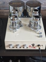
Hi Zintolo, thanks for your quick reply. I use V+=450V and VBdc -110V and C10 allows 150V. I think I need to change the shunt resistor R13 from 27k to 22k or bether 18k. Logically, that should balance better. Or do you have another idea? What about the R18?With about 1.1k, he should be able to dissipate the cathodes better via the LEDs and dampen the signal less.... Do you have any experience with this? Greetings from Berlin, Timo PS Thats my project 🙂
Attachments
R16 is ok.
R13 is needed to be adjusted based on the tubes you use, the loadline you have chosen, the UL percentage, etc...
R18 is IMO too high at 1k1, especially if you look for higher feedback ratios through R13.
Nice project Timo!
R13 is needed to be adjusted based on the tubes you use, the loadline you have chosen, the UL percentage, etc...
R18 is IMO too high at 1k1, especially if you look for higher feedback ratios through R13.
Nice project Timo!
Good morning,
One more thing about resistors R13, R16 and R18
After reading pretty much all the threads about these resistors, I'd like to share my experiences. I made many attempts with different values.
The shunt resistor R13 has a great influence on the "tube sound" of the device and if you prefer the amp to sound like a transistor radio, you should set the value to 17k to 20k. From 25k the amp starts to sound beautifully musical.
My setup with 2 LEDs and R16 with 56k is quite ok so far.
But then I looked at R18. I replace this with a 1k precision trimmer. But ATTENTION! This should be preset to 800 ohms! Most ECC83 work effectively according to characteristic curves with Ua = 250V and Ia = 1.2mA.
So I was able to set the ECC83 exactly. Good results then on the TP10 (anode) at Va 245V and an Ia of 1.8mA and the amp sounds very good.
Have fun trying it out.
Have a nice day
Hi Timo,
based on my experience the CCS works better with a fixed resistor plus a trimmer. This way you can safely and more accurately set the current using the full range of the trimmer.
Just one point: your 1.8 mA is not the Ia of one triode, but the sum of the Ik (that is equal to the sum of the two Ia in most cases) of the two triodes.
When you report values, please report your full schematic, otherwise people can be hijacked not considering your full scenario.
Hi All,
Just few technical questions about the phase inverter in this circuit.
If I intend to open the circuit (feedback 1 & 2) so signal input pin 7 of ECC83 is grounded, then how the two 180 out of phase signal could be setup for the PP output tubes ?
Because i only understand this cct. where is the Preamp + (phase Inverter) + Driver + Output and its function, but i don't know where & how the phase inverter portion :< Does it not exist or any other way to be done ?
CK
- Home
- Amplifiers
- Tubes / Valves
- EL34 Baby Huey Amplifier