And we see another bump when the tube gives up being saturated, so the FET finishes the job. You can get such a way even more power increasing both B+ and the voltage on the control grid, to give more voltage for the FET to swing.

When in the design phase I did increase the G1 voltage slowly until no additional max power was made. I also chose the operating point to preserve the el34 dissipation. I’m definitely sure more power is available from a hotter operating point and more grid voltage with a different tube. Like a kt88 for example. But for that I’d need a more powerful power transformer and bigger heat sinks on the FETs etc. My goal of 10w is ok for this amp I think. Maybe a more powerful version in the future? 🙂
Next up is this Russian 6L6 the 6P3S. It was beyond it's max dissipation and drawing heavy G1 current. Still it did not reach 10W and left A1 operation at only 1.5W
I’m not brave enough to leave it in the amp long term.

I’m not brave enough to leave it in the amp long term.
This Tube is a 6CA7, it's something like an almost kt88. It leaves A1 at a respectable 3.3w but ultimately is higher distortion than the el34 at 10w, 10%THD

And finally, here is the kt120. It makes it all the way to 4.4w before leaving A1 and has the lowest 10w distortion at only 5%. Very nice.

Hi, I found this thread very interesting so had a go at building the amp with what I had available but I've run into problems due to a lack of understanding about the mosfet and its interaction with the EL34.
I used an ECC33 for the first tube and my B+ is about 400v (ie about 50v higher than the schematic).
To get things up and running I used a 100k anode load for the ECC33 along with a 1.9v Led and 510r resistor in the cathode. With 1v rms input to the ECC33 I get about 20.7v rms going into the mosfet. So far so good.
My problem is (given my B+ is ~400v) that I cannot bias the mosfet grid at 8.5v without exceeding the 25w dissipation rating for the EL34. The implication seems to be I only get about 5w output from the EL34 afterwich the mosfet appears to be overdriven.
I thought increasing R113 (51r) would be the answer to increasing the mosfet grid bias but I was wrong.
Can a smart person help a newbie please? 🤔
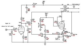
I've attached a snip of the original schematic for reference.
Thank you
Andrew
I used an ECC33 for the first tube and my B+ is about 400v (ie about 50v higher than the schematic).
To get things up and running I used a 100k anode load for the ECC33 along with a 1.9v Led and 510r resistor in the cathode. With 1v rms input to the ECC33 I get about 20.7v rms going into the mosfet. So far so good.
My problem is (given my B+ is ~400v) that I cannot bias the mosfet grid at 8.5v without exceeding the 25w dissipation rating for the EL34. The implication seems to be I only get about 5w output from the EL34 afterwich the mosfet appears to be overdriven.
I thought increasing R113 (51r) would be the answer to increasing the mosfet grid bias but I was wrong.
Can a smart person help a newbie please? 🤔
I've attached a snip of the original schematic for reference.
Thank you
Andrew
Attachments
Just an update.
I increased R113 to 68r and set the 'Bias TP' to 4.8v. That gave me 8.4v on the mosfet grid. The EL34 was dissipating 24w and managed 8w rms output. It seems I'm on the right path...
I increased R113 to 68r and set the 'Bias TP' to 4.8v. That gave me 8.4v on the mosfet grid. The EL34 was dissipating 24w and managed 8w rms output. It seems I'm on the right path...
This is the plot of KT120 triode done by Sofia

But why to run the tubes in A2?
Not reason, in my opinion
Walter
But why to run the tubes in A2?
Not reason, in my opinion
Walter
The bias adjustment pot is where you should be able to adjust the current through the tube and mosfet. If you’re using a enhancement type you should be able to adjust the gate down to the source and 100% stop the current flow (don’t do that because it will cause the tube cathode voltage to rise to the supply). So I don’t understand why you are struggling to limit the current in your version of the circuit. Perhaps you could post a schematic of your implementation.Hi, I found this thread very interesting so had a go at building the amp with what I had available but I've run into problems due to a lack of understanding about the mosfet and its interaction with the EL34.
I used an ECC33 for the first tube and my B+ is about 400v (ie about 50v higher than the schematic).
To get things up and running I used a 100k anode load for the ECC33 along with a 1.9v Led and 510r resistor in the cathode. With 1v rms input to the ECC33 I get about 20.7v rms going into the mosfet. So far so good.
My problem is (given my B+ is ~400v) that I cannot bias the mosfet grid at 8.5v without exceeding the 25w dissipation rating for the EL34. The implication seems to be I only get about 5w output from the EL34 afterwich the mosfet appears to be overdriven.
I thought increasing R113 (51r) would be the answer to increasing the mosfet grid bias but I was wrong.
Can a smart person help a newbie please? 🤔
I've attached a snip of the original schematic for reference.
Thank you
Andrew
In response to Walter’s question about why someone would want to run A2. It’s because it’s fun and that’s the point of hobbies. Or at least that’s why I designed this amp.
Also it’s been the better part of a year so here’s a boring update. The amp gets used most days and hasn’t had any problems. Sounds great to me.

Thanks Doug.
I really appreciate your work and have watched all your youtube videos!
I agree the amp does sound very good. I have a little bit of ringing on a square wave at the output but I will have to think about that later.
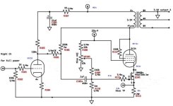
I'm using the same mosfet as your schematic (see attached with my changes and voltages in blue).
What I don't really understand is the relationship between the EL34 operating point and the mosfet grid voltage. I think I need to increase the mosfet grid voltage to achieve the 10w amp output that you get (currently I get 8w) but by increasing the mosfet grid, I get too much current through the EL34 and exceed it's dissipation rating. That is why I increased R113 from 51r to 69r. Presumably I need to increase R113 further.
I have no training in anything electronic (I'm a civil engineer) but I have learnt a few things tube related over the years whilst avoiding anything transistor or mosfet related!
Andrew
I really appreciate your work and have watched all your youtube videos!
I agree the amp does sound very good. I have a little bit of ringing on a square wave at the output but I will have to think about that later.
I'm using the same mosfet as your schematic (see attached with my changes and voltages in blue).
What I don't really understand is the relationship between the EL34 operating point and the mosfet grid voltage. I think I need to increase the mosfet grid voltage to achieve the 10w amp output that you get (currently I get 8w) but by increasing the mosfet grid, I get too much current through the EL34 and exceed it's dissipation rating. That is why I increased R113 from 51r to 69r. Presumably I need to increase R113 further.
I have no training in anything electronic (I'm a civil engineer) but I have learnt a few things tube related over the years whilst avoiding anything transistor or mosfet related!
Andrew
Attachments
Of course it is funny to try some other wayIn response to Walter’s question
But some considerations.
This is a THD vs lev of a s.e. 2A3, little power good OT, etc.
is possible to see the historic andament, soft, of the curve, practically no saturation until the max level permitted by the test.
0 dB is the nominal power, around 2,5 watt.
This is the curve of a big ss, Halcro, good amp well designed
The shape of the curve is quite similar of the EL34 in A2 with the use of the sand. The power is different, of course
Normally in ss amps the the THD increase quickly when the level reach the clipping that is immediately
So my opinion is that there isn't reason to made stuff with tube when they act similar to ss.
Much better to spent time and money to develop and test ( or buy) a great OT trafos where in this case the job is strong.
At the end if there aren't curves ,with 34 or 88 family, some reason there are must be
But it only my opinion
Walter
Drew, R113 should not be increased. It has several functions but its value actually limits maximum power so I’ve actually used the lowest value I felt comfortable with.
The current through the MOSFET and tube should be set for maximum dissipation of the tube using the biasing pot.
If you are not achieving the same power I am I’d check and make sure your +25v supply to g1 is sufficiently low Z. Also because you are using a different operating point (higher B+) your results may be different.
It would help if you could draw out your whole circuit for us.
Walter, I disagree that this causes the amp to become more like a solid state amp. I believe this amp behaves identically to a class A SE amp right up to the point where a normal class A circuit would clip. In the traditional class A SE circuit it would clip hard as G1 hits 0v. However in this amp there are instead several more watts of what may be considered very soft clipping aka A2 operation. In my graphs of power vs distortion the point at which A2 operation begins there is a marked and steep rise in distortion yes, but if compared to a graph of the same amp without A2 operation the rise in distortion would basically be vertical at the point when G1 asks for current that is not available.
Are different opinion but the most important things is to be happy to test.Walter, I disagree that this causes the amp to become more like a solid state amp
I avoid the use of sand in each active amp stage. Orror!!!!!!!!!!!!!!
🙂
Just in the power supply for convenience.
Walter
Hi Doug,
I've been tied up on other things hence my slow response time.
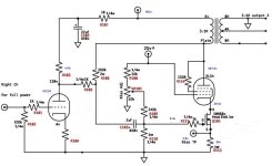
I think the issue is my B+ is higher hence I need to increase R113 a little. I've used your design but shown my changes/values in blue (see attachment). My 25 volt supply is identical to you schematic with the same components.
The other interesting change is the use of an ECC33. At the moment it is biased with a red LED at 1.9v but I am thinking about replacing that with a resistor.
As shown in the attachment, I get 70.6mA through the EL34 which equates to 23.8 watts dissipation and 8 watts RMS audio out.
I ordered the same transformers you specified earlier in post #14 of this thread. The performance is very impressive.
I have a pair of Svetlana EL34's which sound great. Relative to 1kHz i get -1.9dB at 10Hz and -1.8dB at 20kHz. I do have some apparent 45kHz ringing on a square wave that I need to resolve.
I'm yet to measure the performance with Goldlion KT77's but to me they sound even better than the EL34's.
Great design Doug!
Andrew
I've been tied up on other things hence my slow response time.
I think the issue is my B+ is higher hence I need to increase R113 a little. I've used your design but shown my changes/values in blue (see attachment). My 25 volt supply is identical to you schematic with the same components.
The other interesting change is the use of an ECC33. At the moment it is biased with a red LED at 1.9v but I am thinking about replacing that with a resistor.
As shown in the attachment, I get 70.6mA through the EL34 which equates to 23.8 watts dissipation and 8 watts RMS audio out.
I ordered the same transformers you specified earlier in post #14 of this thread. The performance is very impressive.
I have a pair of Svetlana EL34's which sound great. Relative to 1kHz i get -1.9dB at 10Hz and -1.8dB at 20kHz. I do have some apparent 45kHz ringing on a square wave that I need to resolve.
I'm yet to measure the performance with Goldlion KT77's but to me they sound even better than the EL34's.
Great design Doug!
Andrew
Attachments
- Home
- Amplifiers
- Tubes / Valves
- EL34 A2 Cascode SE triode