Also following this design with interest. The Mosfet in the schematic 10N60C seems to be obsolete. Will this one work in its place?
https://www.mouser.com/ProductDetail/STMicroelectronics/STP10N60M2?qs=DqCdCwOw4/5AmMf4xasHww==
Is this based on the Tubelab UNSET, or am I confused?
https://www.mouser.com/ProductDetail/STMicroelectronics/STP10N60M2?qs=DqCdCwOw4/5AmMf4xasHww==
Is this based on the Tubelab UNSET, or am I confused?

That MOSFET isn’t rated for DC in the SOA so I’d look for one that can handle DC. 600v is unnecessary and RDS ON is not important in this application. 400v is more than sufficient. The 10N60 is still available.
I was unaware of TubeLab’s UNSET when I designed this and any similarities are coincidental.
I was unaware of TubeLab’s UNSET when I designed this and any similarities are coincidental.
Preliminary test results. Here is calibrated voltage noise into 8R. The amp input is shorted. All hum components below 100uV. Pretty good for SE cascode with AC heaters. PSRR is very poor.

There are similar bits, like the operation of the output tube in common g1, but apart from that is pretty different. There is no direct feedback (both DC and AC) from plate to g1, feels like a Schade-style feedback from plate to plate. Then the driving mosfet is not a follower, it is an amplifying stage. Then it has feedback from the output windings to the driving mosfet.Is this based on the Tubelab UNSET, or am I confused?
Thanks for pointing out the differences @jcalvarez. I see some similarities which I appreciate. Intriguing work gentlemen.
@Doug De Young, if you have not looked at it yet you might find the Tubelab UNSET development interesting. See here: https://www.diyaudio.com/community/threads/unset-beta-board-build.376124/page-29#post-7645393
@Doug De Young, if you have not looked at it yet you might find the Tubelab UNSET development interesting. See here: https://www.diyaudio.com/community/threads/unset-beta-board-build.376124/page-29#post-7645393
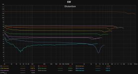
Measurements finished up.
Attachments
-
 1w FFT Rch 8R.jpg315 KB · Views: 80
 -
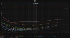 1W.jpg316.6 KB · Views: 79
 -
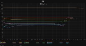
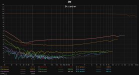 2W.jpg322.7 KB · Views: 71
 -
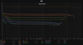
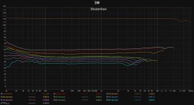 3W.jpg300.7 KB · Views: 71
 -
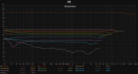 4W.jpg292.8 KB · Views: 75
 -
 6W.jpg290 KB · Views: 73
 -
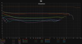
 5W.jpg286.3 KB · Views: 73
 -
 7W.jpg289.1 KB · Views: 80
 -
 8W.jpg290.2 KB · Views: 79
 -
 9W.jpg290.1 KB · Views: 86
 -
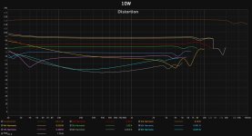 10W.jpg292.2 KB · Views: 88
 -
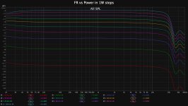 FR vs Power 1-10W.jpg308.8 KB · Views: 76
 -
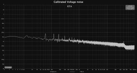 Calibrated voltage noise Rch 8R.jpg172.4 KB · Views: 82
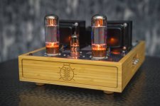
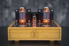
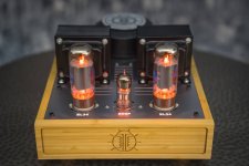
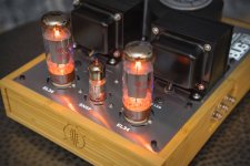
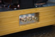
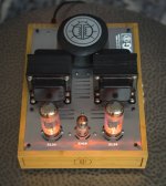
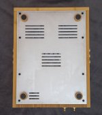
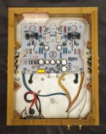
Also some nice photos of the finished build
Attachments
-
 DUG09589.jpg229.5 KB · Views: 100
 -
 DUG09591.jpg212.6 KB · Views: 100
 -
 DUG09592.jpg209.5 KB · Views: 97
 -
 DUG09593.jpg248.4 KB · Views: 89
 -
 DUG09595.jpg201.2 KB · Views: 101
 -
 DUG09596.jpg296.5 KB · Views: 97
 -
 DUG09597.jpg255.1 KB · Views: 101
 -
 DUG09598.jpg221.4 KB · Views: 87
 -
 DUG09599.jpg483.1 KB · Views: 106
 -
 DUG09600.jpg562.4 KB · Views: 113
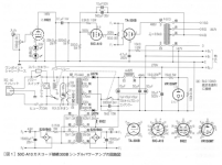
All tube version of se cascode output from the "goldmine" thread on this forum:
https://www.diyaudio.com/community/attachments/ta300b-png.783034/
https://www.diyaudio.com/community/attachments/ta300b-png.783034/
Attachments
Still deciding what to do about offering up the PCBs and such. You’re of course welcome to use the circuit to develop your own PCBs in the meantime if you want.can you share the gerbers?
Very cool!All tube version of se cascode output from the "goldmine" thread on this forum:
https://www.diyaudio.com/community/attachments/ta300b-png.783034/
I’d probably go with a pentode on the bottom if I was designing. But don’t have a ton of experience with cascode output stages. I’ve only designed one! 😂
Congrats. Have you considered using this drive circuit with a GU-50 in SE?
- Home
- Amplifiers
- Tubes / Valves
- EL34 A2 Cascode SE triode