That’s great you used my 25v supply! Did you also include the LEDs that indicate the transition to A2 operation?
I still don’t believe you should increase the value of r113.
I also see you’ve eliminated the second FB loop that linearizes the output transformer. That may be why you’re experiencing some slight HF roll off.
I still don’t believe you should increase the value of r113.
I also see you’ve eliminated the second FB loop that linearizes the output transformer. That may be why you’re experiencing some slight HF roll off.
Yes, the 25v supply is identical including the LEDs that indicate A2 operation.
I am struggling to understand how the fet works (it a me thing). If I set R113 at 68r then I get a funny distortion in a sine wave well before I get any A2 current. If I set at R113 at 51r then I get a clean a sine wave with A2 current at the pint of clipping. I not sure why the first scenario doesn't draw A2 current but the second does.
Anyway, with R113 = 51r and the TP set to 4.080v, my EL34 is dissipating 27w with 80ma of current through the tube (Va=387.3v, vk=49.68v).
With CFB connected, measure 9.0w rms. -3dB points at 1 watt are 6Hz and 22.1kHz.

Possible that you’re experiencing some oscillation. In my circuit c101 was necessary to ensure stability. Also the stopper on the FET gate should be right on the pin.
9w is pretty close to my measurement.
9w is pretty close to my measurement.
Thanks Doug, I've review the stopper proximity to the FET (currently about an inch away).
Using KT77's:
Power out is 8.8w with CFB
TP = 4.045v
Tube current is 79.3ma
Tube dissipation is 27.4w (I'm working on the plate plus the screen in triode gives me a max allowable of 28w)
Sound is amazing!
Using KT77's:
Power out is 8.8w with CFB
TP = 4.045v
Tube current is 79.3ma
Tube dissipation is 27.4w (I'm working on the plate plus the screen in triode gives me a max allowable of 28w)
Sound is amazing!
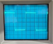
That’s pretty minimal really. I think mine looked similar. All the FR and distortion in the audio range was fine though. None of us are actually inputting the leading edge of a square wave during music listening. That’s very high frequency content.
Not to downplay the usefulness of a square wave for testing. I use one all the time for a first pass look at the total frequency response of a circuit. However when it comes to music reproduction I trust frequency/distortion sweeps to tell the real story. So to speak.
Not to downplay the usefulness of a square wave for testing. I use one all the time for a first pass look at the total frequency response of a circuit. However when it comes to music reproduction I trust frequency/distortion sweeps to tell the real story. So to speak.
If the ringing is minor and doesn’t show up in the frequency response sweeps in the audio band I don’t worry about it. The likely culprit is the budget AliExpress output transformers so it’s not as simple as tweaking the feedback network. If it was just a bit of overshoot at the leading edge well placed cap would take care of it but it’s a bit more than that. From my own experience making compensation networks for transformers I think this square is probably just fine. Others will have different opinions I’m sure.
Grid of el34 is AC grounded.
Grid of el34 is AC grounded.
"Grid of el34 is AC grounded."
Neither the amp schematic, nor +25V PSU schematic doesn't indicate this.
Neither the amp schematic, nor +25V PSU schematic doesn't indicate this.
The 25v supply is regulated in reference to GND. So it’s very low Z in reference to GND. This is what it means to be AC grounded.
It is ac grounded because you have on power supply the last cap not for low ZThis is what it means to be AC grounded.
Walter
Simulating +25V PSU, it's output impedance -with good FET- about 16R... but rising above 10k.
For safety's sake I would place capacitor to g1.
For safety's sake I would place capacitor to g1.
The reason why I didn’t place a cap there is because it would create a RC between the output Z of the FET and the trace and cap. It would also cause some of the instantaneous g1 current to be sourced from the cap and not through the LED. Though it probably would have not been an issue.
In any case, g1 having a 16R Z to gnd is near enough to zero. When in the design phase I did place a cap in that position but later removed it.
I’ve posted detailed measurements a few pages back. What difference would you expect to see if I soldered a cap in that position? Perhaps on entering A2 g1 would be held at 25v for a fraction of a second longer before settling down to 24.9v? Or maybe a small signal present at g1 during A2 operation would be eliminated. It’s possible the distortion in the A2 region would be slightly lower. I’d have to test it.
Could I ask primary DC resistance, frequency response, mA & how many output taps: 4,8,16 etc.It’s a pair. The shipping can be quite high though. Still it’s pretty good value.
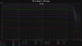
DCR is around 115R I think. 0-4-8 secondary. I’m running 88ma. You can see my detailed FR vs Power graph in an earlier post but here it is again. This is only the FR in this particular circuit though and more performance may be available in a different circuit.
Attachments
- Home
- Amplifiers
- Tubes / Valves
- EL34 A2 Cascode SE triode