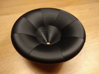
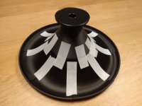
Indianjo, you talking about
I would love to hear a speaker like that. Must offer much better performance than the Devore's. For $599 they look to offer performance that would blow away most $5,000 audiophile speakers.
Hi Tom, good question. I would also like to know that answer. Is from Stereophile's measurements. The response was something like it ran above the normal 8 ohm speaker so that gave apparent reduction in efficiency. Though Stereophile never did provide subsequent compensated measurements.
Stereophile also justified their poor measurements by saying they measured the same bad results with Audio Note as well. So that made it okay.
Peavey SP2 15" 2-Way Passive Loudspeaker
https://www.pssl.com/products/peavey-sp-2-passive-speakerI would love to hear a speaker like that. Must offer much better performance than the Devore's. For $599 they look to offer performance that would blow away most $5,000 audiophile speakers.
Hi Tom, good question. I would also like to know that answer. Is from Stereophile's measurements. The response was something like it ran above the normal 8 ohm speaker so that gave apparent reduction in efficiency. Though Stereophile never did provide subsequent compensated measurements.
Stereophile also justified their poor measurements by saying they measured the same bad results with Audio Note as well. So that made it okay.
Last edited:
The modern 2000 w peak 1000 w AES version is not as hifi as the SP2(2004) version I have. Mine are 500 w AES. The spec sheet charts 2nd & 3rd harmonic distortion 20 db down from response @ 1 % power (5 W). 3rd harmonic HD chart is 50-8 khz, and the 2nd chart 50-12 khz.Indianjo, you talking about
Peavey SP2 15" 2-Way Passive Loudspeaker
A piano CD really sounds like a Steinway grand, pretty closely. Which is why I bought them. I've never heard any other speaker sound close to a piano in this flyover state. Maybe the MeyerSound at Brown Theater, the size of micro autos. Reason I'm building, SP2 have pawn shop value & my SP2-XT were stolen 9/19. I can build some speaker really ugly, not worth stealing. Also in the 9 months it took to find the used SP2(2004) I had bought the woofers CD tweeters horns & some passive crossover parts. Now need a table saw.
Last edited:
This thread had been a bit silent, but I've been busy. Mostly I've been reading about waveguides and been busy with and around Ath.
In the mean time I've bought a 3D printer and I put that to work printing a waveguide design I made with Ath.
Here are some samples:
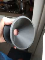
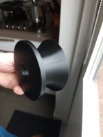
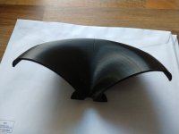
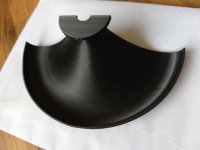
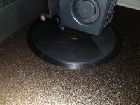
They look great, but there are also some problems. I have some warping, so the two halves (scale 1:3) do not fit nicely together. That is made worse by a small shift at some height. The full scale throat edges didn't stick to the bed and warped. And then there is the blistering that doesn't really show when it's finished.
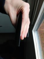
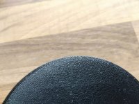
I guess the next step is buying some drivers. Lots of work to do in all areas 🙂
In the mean time I've bought a 3D printer and I put that to work printing a waveguide design I made with Ath.
Here are some samples:


They look great, but there are also some problems. I have some warping, so the two halves (scale 1:3) do not fit nicely together. That is made worse by a small shift at some height. The full scale throat edges didn't stick to the bed and warped. And then there is the blistering that doesn't really show when it's finished.


I guess the next step is buying some drivers. Lots of work to do in all areas 🙂
Elegoo Neptune 2S. Put it together and started printing. My 10-year old daughter can download a model from thingiverse, slice and print it. 🙂
Now addressing the above 'problems'. We'll see.
Any advice on how to connect/glue the petals? 3D print a tool? Add some extra features for lining up of everything? Or for screwing them together?
Now addressing the above 'problems'. We'll see.
Any advice on how to connect/glue the petals? 3D print a tool? Add some extra features for lining up of everything? Or for screwing them together?
I think everyone just needs to find their way - you either start by adding the petals to the base (then it's important to ensure the first one being at the correct angle) or make the whole ring and attach that to the base. The glue can be crucial for a good result - something correctable for a while is definitely a good thing.
Gel type CA glue works pretty good both for PLA and PETG. And allows for some slight adjustment. If filling is necessary (and it usually is), then liquid nail type glue is the best - Pattex 1 for all or Mamut glue holds the prints well and fill the gaps. You need some kind of fixture for these - strategically placed pieces of tape will do. I recommend doing dry fitting with tape first.
I don't know where to ask this question, so I'll just do it here.
I've tried to read Geddes' chapter 6 several times now. Some parts start to make sense, others are still way over my head. I understand that he wants to limit HOM's by limiting diffraction. Diffraction is limited by slowly changing the angle of the waveguide. Small gradual changes over the full distance seem to be preferred over a sudden localized change. The OS is said to be the best. Diffraction is said to be 'caused' by the second derivative/curvature. But I don't see how you get to the OS. In case of constant second derivative I would expect a parabola, for constant curvature a circle. Or should the second derivative/curvature be multiplied by 2*pi*r and should that be kept small? Seems to make sense. Quick angle change at the throat where the radius is small, slowly changing angle more towards the mouth where the radius is larger.
Does any of this really make sense?
The petal was printed very nice.
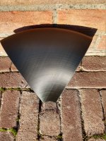
It's even better then the throat. You can barely see or feel the individual layers. The connection to the throat is not completely flat and the petals are quite large. The contact area is also quite small, so I think I will make the throat piece bigger (and the petals smaller). The z seam is at the sharpest edge, not the best place I guess (sound side of connection to throat piece).
I need a brim to keep the part attached to the bed. The biggest 'defect' is from that.
I pre-bought a pair of HF108's yesterday. Deal will be closed after carnaval.
I would recommend to print also some gluing guide. This is how it looks like when gluing free hand🙂 I did not pay much attention to this, it was just a test.

Yes, the brim needs to be cut off carefully not to have the "elephant foot" effect.
Yes, the brim needs to be cut off carefully not to have the "elephant foot" effect.
I tried another way to make the alignment easier by using a groove and making the top piece a different cross section to avoid needing to use supports. My test print was small so it could be all in one but I still think it would be easier to make and align nicely this way, less opportunity for warping.
https://www.diyaudio.com/community/...-design-the-easy-way-ath4.338806/post-6750632
https://www.diyaudio.com/community/...-design-the-easy-way-ath4.338806/post-6750632
Interesting approach fluid. Always interested in other people's ideas.
I made the throat and petal completely separately in Fusion 360 and I kinda messed up. Petals don't fit the throat. 😳
I taped two (well actually 1.5) petals together. It's kind of a pitty that a petal is so smooth and the joining of them is not that great.
I made the throat and petal completely separately in Fusion 360 and I kinda messed up. Petals don't fit the throat. 😳
I taped two (well actually 1.5) petals together. It's kind of a pitty that a petal is so smooth and the joining of them is not that great.
That was my thinking that the stiffer I could make the parts and use mechanical alignment the less sanding and smoothing I would have to do afterwards.I taped two (well actually 1.5) petals together. It's kind of a pitty that a petal is so smooth and the joining of them is not that great.
I don't know if the V on the inside of the rollback has any real negative effect but it makes the petal part stronger and more accurate.
I made the model by revolving a profile and then cut it up afterwards with some tolerance added to make sure it would all fit back together. There was a slight lip at the join from printing separately but less than layer so easy to remove. There is also a very large glue surface which should also help.
With enough filler, sandpaper and time most things could be made to look nice but I really hate sanding and filling.
P.S I'm no 3D printing expert but the first layer doesn't look as good as it could be in the photos above, the printer might need a little bit of calibration to get the best out of it.
Would you be so kind to indicate in the photos what you mean and eleborate a bit more on what would need calibration?P.S I'm no 3D printing expert but the first layer doesn't look as good as it could be in the photos above, the printer might need a little bit of calibration to get the best out of it.
I'm using a brim to enhance bed adhesion, but don't like the result after removal of it. It does it's job though, bed adhesion is fine now and without it wasn't.
It's not super easy to show in the photos and it could be partly due to the texture of the bed. Poor bed adhesion can be linked to getting the first layer wrong as everything builds from there.Would you be so kind to indicate in the photos what you mean and eleborate a bit more on what would need calibration?
I'm using a brim to enhance bed adhesion, but don't like the result after removal of it. It does it's job though, bed adhesion is fine now and without it wasn't.
Prusa has some good calibration and troubleshooting guides
https://help.prusa3d.com/en/category/calibration_199
https://help.prusa3d.com/en/category/print-quality-troubleshooting_225
It's worth running a few calibration steps to make sure the printer is dialled in as well as it can be, overall the print quality looks nice 🙂
I can help you make a model in Fusion360 which I find to be the most intuitive of the decent CAD programs.Probably need to follow some of fluid's advice, but need to get my head around CAD software. Somehow I don't find them intuitive.
I converted the ABEC3 output for my R-OSSE waveguide to VituixCAD input using a custom Octave script. I had to scale the power of the CD (50dB). I then let VituixCAD optimize for the preference rating. This is the result:
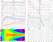
Can someone say something smart? Any problems? Any anything? I miss the overview...

Can someone say something smart? Any problems? Any anything? I miss the overview...
It looks like you have not compensated for the waveguide gain / mass roll off which is why your on axis and listening window is sloped down and leaves a hump where it crosses to the woofer.
Have a look at this post where there is an image and link to a document that explains it. A simple first order filter with a frequency of 20K or so usually work to counteract the gain well enough.
https://www.audiosciencereview.com/.../revel-m105-copy-diy-build.29465/post-1030095
Have a look at this post where there is an image and link to a document that explains it. A simple first order filter with a frequency of 20K or so usually work to counteract the gain well enough.
https://www.audiosciencereview.com/.../revel-m105-copy-diy-build.29465/post-1030095
- Home
- Loudspeakers
- Multi-Way
- Efficient 2-way
