That has a patent?
Couldn't pay me to listen to that. Just goes to show how worthless patents can be. Yes, it may be low impedance, but........
Jocko
Couldn't pay me to listen to that. Just goes to show how worthless patents can be. Yes, it may be low impedance, but........
Jocko
You're still gonna have the same problem....
The load resistor is in series with the collector. You need to put a current source there and set the gain with a load resistor.
I ain't gonna 'splain this again.
Jocko
The load resistor is in series with the collector. You need to put a current source there and set the gain with a load resistor.
I ain't gonna 'splain this again.
Jocko
regarding the simulations
tschrama
if you replace the ideal voltage source biasing your
Q3 base in the "cas" schematics with real world
sources, such as resistors, diodes zeners etc, you will find that
the distortion will be more realisitic ie higher.
Yv
tschrama
if you replace the ideal voltage source biasing your
Q3 base in the "cas" schematics with real world
sources, such as resistors, diodes zeners etc, you will find that
the distortion will be more realisitic ie higher.
Yv
I-V Stage
Hi Tschrama,
You almost have built a current feedback amplifier!
These might have certain advantages in this particular application. See f.a. the AD844 datasheet.😉 Sonically I was not impressed by these CFB-amps😉
Hi Tschrama,
You almost have built a current feedback amplifier!
These might have certain advantages in this particular application. See f.a. the AD844 datasheet.😉 Sonically I was not impressed by these CFB-amps😉
I think you'll find IV stage bjt and cas2, the ones with both PNP and NPN transistors isn't going to work very well. The bias through the input transistors will be virtually impossible to set and get stable unless you put resistors at the emitters but that raises input impedance.
Spying on me again, eh, Elso?
The reason why I came up with my top-secret I/V is that I was using AD846s for them in several designs. Sounded great, but only up to a point. And the point was that the dealers hated them. So........get rid of the feedback, and voila!
Yes......I know.....I keep saying it.......current-feedback stuff sounds odd. Don't know why.
As for being stable..........then how do things like the AD844/846, and all those other similar ICs work. Yeah, I know.......matched parts on the same substrate, etc. There are ways around it.
Jocko
Just the other day I was playing with THIS circuit in Microcap 😛 ;
See http://www.diyaudio.com/forums/show...132&perpage=15&highlight=purists&pagenumber=2
It just happens to be exactly the input stage of the AD846
 😀
😀
With very careful matching and resistor tuning DC coupling is possible.
See http://www.diyaudio.com/forums/show...132&perpage=15&highlight=purists&pagenumber=2
It just happens to be exactly the input stage of the AD846
😀With very careful matching and resistor tuning DC coupling is possible.
Attachments
Hi,
Many people already tried this topology. Here is some good reading from one already tried this.
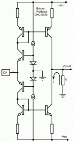
It is in fact a common base circuit. One note of caution: A small parasitic capacitor from the emitter to ground will definitely turn this circuit into a hf oscillator. Depends a bit on the emitter bulk resistance and Ft. Who was saying this circuit has no feedback? Although a DAC-chip is current out, most have a pretty low output resistance in the order of 1K, take it into account. It interferes with input resistance at the emitter. The current flowing into the emitter modulates its resistance. For low distortion, the current trough the bias diode at the base should have the same current flowing trough it as the emitter that is driven at ALL signal levels and the construction should preferably be build with matched pairs.
If you want to investigate this further, have a look at the BurrBrown OPA660 “diamond” transistor. PSpice model is available Looks promising, but no idea how it sounds.
Many people already tried this topology. Here is some good reading from one already tried this.
It is in fact a common base circuit. One note of caution: A small parasitic capacitor from the emitter to ground will definitely turn this circuit into a hf oscillator. Depends a bit on the emitter bulk resistance and Ft. Who was saying this circuit has no feedback? Although a DAC-chip is current out, most have a pretty low output resistance in the order of 1K, take it into account. It interferes with input resistance at the emitter. The current flowing into the emitter modulates its resistance. For low distortion, the current trough the bias diode at the base should have the same current flowing trough it as the emitter that is driven at ALL signal levels and the construction should preferably be build with matched pairs.
If you want to investigate this further, have a look at the BurrBrown OPA660 “diamond” transistor. PSpice model is available
Looks promising, but no idea how it sounds.JOCKO'S BEST POST EVER.
Hi guys,
And would you believe I get accused of playing with peoples' minds in the "Tubes" section?
Whilst recovering,
Hi guys,
Try changing the 1000 K resistor in series with the input, and change it to 1000 or 1 K (either one works!......it is a joke......). Then try putting 4 V rms into that thing.
And would you believe I get accused of playing with peoples' minds in the "Tubes" section?
Whilst recovering,
oscillator- how?
Pjotr,
What is the reason for the oscillation when a cap
is connected at the emiiters at the input?
I am missing something here. Would you enlighten?
TIA
Yv
Pjotr,
What is the reason for the oscillation when a cap
is connected at the emiiters at the input?
I am missing something here. Would you enlighten?
TIA
Yv
I thought the Bordeaux-Claret was the best one. Until Phred blew the punchline.
Hey.....I didn't put 1 Megohm there.
Thanks to Pjotr for the link. Glad someone is paying attention. Even Barrie Gilbert (Gilbert Cell fame) says that an op-amp is the worst thing you can put after an R-2R DAC.
Jocko
Hey.....I didn't put 1 Megohm there.
Thanks to Pjotr for the link. Glad someone is paying attention. Even Barrie Gilbert (Gilbert Cell fame) says that an op-amp is the worst thing you can put after an R-2R DAC.
Jocko
What is the reason for the oscillation when a cap is connected at the emiiters at the input?
If the base of a transistor is driven by a nonideal source, (ie some resistance in series with the base) the emitter looks somewhat inductive to the circuit attached to it. In other words, the impedance looking into the emitter increases with frequency. Keep in mind that even if you nail the external base termainla of the transistor down with a solid low impedance, there is internal base resistance.
The effective inductance is approximately Cpi * Rpi * (Rb/Beta), where
Cpi = Tf/Gm, Rpi = 1/Gm, Gm = Ic/Vt, Vt = kT/q = 26 mV at room temp, Ic is the collector current, Rb is the total internal+external base resistance.
The total output impedance can be estimated as this inductance in series with an equivalent "resistance" of 1/Gm+Rb/Beta, and the LR series thing appears in parallel with Rb.
So the upshot is you have someting like an LRC circuit at the emitter, with the transistor acting like a fake inductor. Hence the possibiliy of resonances and oscillations.
To understand this intuitively, remember that the base-emitter junction stores a lot of charge, and so it acts like a capacitor. The charge in this junction determines the current flow in the transistor. If you feed the base from a resistive source, it takes time to charge and discharge this base-emitter capacitor, so it takes time to change the current flow in the transistor. Which is exactly what an inductor does; you can't change the current flow instantaneously in an inductor, inductor current varies slowly.
Does this make sense?
JOCKO'S BEST POST EVER and Spice
I believe Jocko's point was that the output of a DAC chip is not an ideal current source but has much lower output impedance than 1 Megaohm. And I would bet money that he has measured this.
Too high an impedance in the Sipce model will act as an unrealistic amount of emitter degenaration and give even lower distortion in the Spice model. I don't know why everyone keeps measuring distortion with Spice as it gives meaningless numbers due to the simplified models used for transistors. I am wasting my breath with that statement I know but someday......
Go build one of the simple Nelson Pass or Erno Borbely circuits from the websites and compare thier measured distortion with the numbers that Spice gives you. I guarantee the discrepency is not due to Nelson or Erno's measurement techniques.
the Spice is quite nice
but it is best to make test
to find out the rest
Haiku.... by who?
Fred
P.S. Thanks go to Poet Warrior Zen Master Pass for the gratuitous Haiku inspiration
Attachments

Yes......I know.....I keep saying it.......current-feedback stuff sounds odd. Don't k
But you do know that it is odd.
What sort of odd ?.
Eric.
But you do know that it is odd.
What sort of odd ?.
Eric.
I don't know why everyone keeps measuring distortion with Spice as it gives meaningless numbers due to the simplified models used for transistors. I am wasting my breath with that statement I know but someday......
Please will you stop whining about PSpice everywhere that comes up in a thread. It is of no use to blame PSpice and people investigating it that YOU get meaningless numbers out of it. Hopefully someday….. you get meaningful numbers out of it too.
I dare to say that you can even predict how an amp will sound, once you manage to use it the correct way. But only if you correlate the results in the correct way with your real life hearing experience, your measurements results and what is already published over the last 50 years about what makes an amp sounds as it sounds.
For those who get rubbish out of it, don’t give up. One day you will recognise why it generates rubbish and why the results do not correlate with the real thing. Then it will start to be a great helpful tool. It helped me a lot to get rid of problems that cannot be isolated in real life. But you need to be aware of the shortcomings of modelling in general and how to handle it and interpret it. That is also called “Learning”.
You can continue here, I hope you don't mind.😉 
http://www.diyaudio.com/forums/showthread.php?s=&postid=79842#post79842
http://www.diyaudio.com/forums/showthread.php?s=&postid=79842#post79842
oscillations
Mirlo
Thanks, the last paragraph nailed it.
It's this kind of stuff that makes the forum great.
cheers
Yv
Mirlo
Thanks, the last paragraph nailed it.
It's this kind of stuff that makes the forum great.
cheers
Yv
I have two questions for jocko and/or others:
Will this circuit work on +/- 14V?
Will it drive output cable direct?
What will be with distortion in this two cases?
Thank you foryour reply,
Aleksander
Will this circuit work on +/- 14V?
Will it drive output cable direct?
What will be with distortion in this two cases?
Thank you foryour reply,
Aleksander
Yes, and yes.......but I would add a buffer for a number of reasons. A simple JFET follower works well here.
Jocko
Jocko
Use with PCM 1738?
Jocko, etc.
How would you configure this circuit for use with a DAC like the PCM 1738 which has 2.5 volts DC on its current outputs. Would you bias the input transistor on its base so there would be 2.5 volts on the emitter? Of course you would use two of these circuits for plus and minus and then sum them through a transformer or other circuit, or just use it single ended. Anyone?
Ric Schultz
- Status
- Not open for further replies.
- Home
- Source & Line
- Digital Source
- Easy-to-build I/V stage