try find 33V in your cd player!? ;O)
hi hi hi
you need an dc blocking cap on your output(-)... then it should work to.
hi hi hi
you need an dc blocking cap on your output(-)... then it should work to.
All,
+33V should be sufficient as B+ for a single ended ECC88/6DJ8 tube stage . Of course, 6.3 V heater supply is needed.

+33V should be sufficient as B+ for a single ended ECC88/6DJ8 tube stage
. Of course, 6.3 V heater supply is needed.I/V stage output voltage
Dice45, Jocko Homo and All,
Thanks for answer.
Not specified (sorry), but my question was for Jocko's I/V circuit.
What is the output voltage for a 0 to 4 mA input current?
Ciao Ciao
Marco
Dice45, Jocko Homo and All,
Thanks for answer.
Not specified (sorry), but my question was for Jocko's I/V circuit.
What is the output voltage for a 0 to 4 mA input current?
Ciao Ciao
Marco
Marco,
I suppose you mean a dac like the TDA1541 which sinks 0~4mA ?
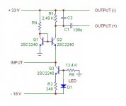
You need to adjust the current source 2mA higher than the current sink, change R1 to something like 1.5K for 2Vrms output.
Also check that 100u capacitor, since with lower R1 there will be more low frequency roll-off.
Rudolf
I suppose you mean a dac like the TDA1541 which sinks 0~4mA ?
You need to adjust the current source 2mA higher than the current sink, change R1 to something like 1.5K for 2Vrms output.
Also check that 100u capacitor, since with lower R1 there will be more low frequency roll-off.
Sonnya, this is incorrect. I use the +V rail as common without problems, it's all relative 🙂you need an dc blocking cap on your output(-)... then it should work to.
Rudolf
Hey Jocko, like the new picture!
Call me old-fashioned, but I've always liked Colin Chapman more than Devo. - Pat
Call me old-fashioned, but I've always liked Colin Chapman more than Devo. - Pat
Would someone please guide to how to adjust current source 2mA higher.
It is R6 I need to change or add diode more in series with D1?
A formula or something would be nice so that I might be able to do it myslef next time.
Flemming
It is R6 I need to change or add diode more in series with D1?
A formula or something would be nice so that I might be able to do it myslef next time.
Flemming
It would be much better to omit current source Q4, because of the d.c. instability; then replace it with 6k resistor (assuming 1.5 mA collector current of Q2.
For the distortion reduction Q2 can be replaced by complementary feedback (SziKlai) pair
For the distortion reduction Q2 can be replaced by complementary feedback (SziKlai) pair
Hi Jocko and all others,
I just got this idea. It is the I/V stage for my latest DAC project...(4th allready.. I'm going to be a real DIY pro one day 😉 )
Sorry Jocko, I didn't measure it.. ain't got no distortion or spectrum analyser, but how do you guys feel about this one? I simulates great....but that's just simulation right?
Greetings,
Thijs
Attachments
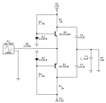
I'm working on something similar......one of these days......but I would imagine something like -40 dB or so distortion with the load in the collector lead.
Jocko
Jocko
Hi,
well thanks for your reply... but -40dB THD seems a bit high for my liking.. any thoughs how to lower this number?
Maybe use a couple of FET instead of the BJTs?
greetings,
Thijs
well thanks for your reply... but -40dB THD seems a bit high for my liking.. any thoughs how to lower this number?
Maybe use a couple of FET instead of the BJTs?
greetings,
Thijs
NO!
The impedance will be too high. The problem isn't the active device......the problem is that the resistor is in series with the active device.
Jocko
The impedance will be too high. The problem isn't the active device......the problem is that the resistor is in series with the active device.
Jocko
Hi Jocko,
I don't understand. Your version has an even higher impedance connected to the colector, being a constant current source. Maybe I should use a CCS too, but wouldn't that increase the gain far too much.....
questions.. questions....
gr,
T
I don't understand. Your version has an even higher impedance connected to the colector, being a constant current source. Maybe I should use a CCS too, but wouldn't that increase the gain far too much.....
questions.. questions....
gr,
T
the CCS would be considered zero impedance, if it were ideal.
Soory if I'm mistaken, but aren't you confusing a constant current source with a constant voltage source?
gr,
T
Oh brother!............(where art thou.....)
A CCS is supposed to be an infinitely high impedance.
Yes, the gain would higher, except that there is a load resistor hanging off of the CCS to set the gain. That method allows for much lower distortion.
Plus, it adds some PSRR to the circuit, as there is no loop feedback.
Jocko
A CCS is supposed to be an infinitely high impedance.
Yes, the gain would higher, except that there is a load resistor hanging off of the CCS to set the gain. That method allows for much lower distortion.
Plus, it adds some PSRR to the circuit, as there is no loop feedback.
Jocko
Oh brother!............(where art thou.....)
HA HA HA HA HA HA HA HA HA HA HA HA HA HA HA HA HA HA
Fred
HA HA HA HA HA HA HA HA HA HA HA HA HA HA HA HA HA HA
Fred
- Status
- Not open for further replies.
- Home
- Source & Line
- Digital Source
- Easy-to-build I/V stage