Re: Oh brother!............(where art thou.....)
Duh. Ignore me when I'm obviously not paying attention.
Jocko Homo said:A CCS is supposed to be an infinitely high impedance.
Duh. Ignore me when I'm obviously not paying attention.
Why don't you guys ever believe me???
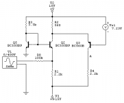
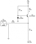
I built this thing......made a few changes........
The load resistors are 3 K, so that you actually get some gain out of it. The resistors for the current mirror were changed to 5 K so that the collector voltage was decent. Raised the rails to +/- 24 V.
With 1.2 mA (peak.....which is what a '1704 puts out) the distortion is.........drum roll, please........
- 40 dB.
Just one problem. That is when you measure it from the collector to ground. When measured between the collectors, it is -23 dB.
So there.
Jocko
Hi Jocko,
Sorry if I gave the impression that I didn't believe you. I just don't understand but I didn't mean I didn't believe it.
Thanks to your reply I finaly got it.. the resistor to ground levels the gain; the bias point is set by the CCS; the CCS lowers Iac?; CCS improve PSRR... thanks for your hints! 🙂
I allways understood that the way to reduce distortion in a simple BJT stage was to
1] decrease Vac (Cascodes do that)
2] decrease Iac (CCS do that)
3] Increase Iq
4] Increase Vce quesient
That why I still don't understand the high distortion in my circuit, maybe add a Cascode for the active devices.
I will go over you comments once more...
gr,
Thijs
PS
My simulator say -90dB distortion 2nd, -100dB distortion 3rd, -120dB all others for 2mA Iq and 2mA AC from the TDA1541.. Iq of I/V stage is about 7mA .. If you measure -40dB then I really am dissipointed

HA HA HA HA HA!!!!!!!!!
I keep telling you guys.........stop using simulators and build this stuff. Simulators will tell you anything you want to hear if you ask it the right way.
Or is that "wrong" way. Either, way.......they lie!!!!!!!!
Jocko
I keep telling you guys.........stop using simulators and build this stuff. Simulators will tell you anything you want to hear if you ask it the right way.
Or is that "wrong" way. Either, way.......they lie!!!!!!!!
Jocko
OK......back to being more serious....
Don't lower the current, the input impedance will rise. A cascode won't help..........unless it is folded.
No more clues.
Jocko
Don't lower the current, the input impedance will rise. A cascode won't help..........unless it is folded.
No more clues.
Jocko
ust one problem. That is when you measure it from the collector to ground. When measured between the collectors, it is -23 dB.
Yep... between collectors it is a nice guitar-effect pedal 😉 called a octave-ditortion unit! realy nice for squiqy solo's 😎
But I though a degree of even harmonic canceling when both active device were working in the same load to ground.
But then again, capacitor introduce even harmonic distortion might cancel ? or add up ??
PS
The diode current mirrors are in no whay optimised! I suspect 40mV offset or about.. better used real BJT mirrors naturaly
gr,
T
Here's another suggestion for you.......
Try changing the 1000 K resistor in series with the input, and change it to 1000 or 1 K (either one works!......it is a joke......). Then try putting 4 V rms into that thing.
And then still tell me your simulator still says - 100 dB distortion.
Jocko
Try changing the 1000 K resistor in series with the input, and change it to 1000 or 1 K (either one works!......it is a joke......). Then try putting 4 V rms into that thing.
And then still tell me your simulator still says - 100 dB distortion.
Jocko
Hi Jocko and all others... I know this will sound absolutely un-reliable, but we know that allready.. so here goes:
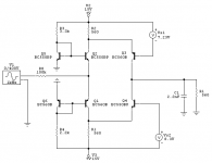
The schematic is only changed in this way:
-changed 1000K input resistor (to simulate current driven output of TDA1541 DAC) to 1K
-changed voltage source to Vbias= +2Volt and Vac = 2Volt peak
I used CircuitMaker2000, 250 points per cycle, 1KHz, fourier up to 10th harmonic
Results:
output = 669.4mV RMS
input impedamce = 2.4 Ohm
Vdc at input = 1.6mV
Vac at input = 3.4mV RMS
Iq BJTs = 6,9mA
Iac BJTs = about 700uA each BJT
Distortion: 2nd = -98dB
3rd = -128dB, all others about -130dB
well..... hows that for a Spice simulation.. unbelieveble I guess....
Why is my simulator giving me this perfect results

gr,
Thijs
The schematic is only changed in this way:
-changed 1000K input resistor (to simulate current driven output of TDA1541 DAC) to 1K
-changed voltage source to Vbias= +2Volt and Vac = 2Volt peak
I used CircuitMaker2000, 250 points per cycle, 1KHz, fourier up to 10th harmonic
Results:
output = 669.4mV RMS
input impedamce = 2.4 Ohm
Vdc at input = 1.6mV
Vac at input = 3.4mV RMS
Iq BJTs = 6,9mA
Iac BJTs = about 700uA each BJT
Distortion: 2nd = -98dB
3rd = -128dB, all others about -130dB
well..... hows that for a Spice simulation.. unbelieveble I guess....
Why is my simulator giving me this perfect results

gr,
Thijs
Hi again,
well just finished my folded-cascode versions.
I simulated both a simple single BJT with folded cascode and a double (like my earlier schematic) with folded cascode.
The nice thing is the circuit can be made DC coupled with low offset, allthough this requires carefull adjustment of the cascode voltage reference (the x-BOSOZ has the same problem, some other thread). The bad thing is that somehow distortion rises to -65dB but all harmonics decay down very nicely from that point on. The output voltage AC ('gain') is very easy to increase by just 1 resistor in the double BJT version, and ias doubled in my single BJT version..
If you want to see a schematic I'll post it for you.
goodnight,
Thijs
😎
Wanted:
one low distortion sine generator
one spectrum analyser
In return:
I can wash your dishes
Wanted:
one low distortion sine generator
one spectrum analyser
In return:
I can wash your dishes
this is what I use now..
about the cascodes: I don't know whether I've done it correctly. I'm quite sure almost anybody can imrpove the circuits.
The cascode are so sensitive for the voltage references that it doesn't seem practicle to build and adjust. I wonder how Nelson Pass it does in his X1000/600 series.
The simulator doesn't show any benifit except for DC coupling and increased bandwidth. The distortion doesn't decrease anymore with the 'parrallel' version neither, while there was a 20dB decrease of doistortion with the cascode-less version when I desighned the ' parrallel' two BJT version...
By now everbody is sleeping ..
well maybe except Jocko..
and I'm awake frustrated about my perfect IVstage that I can't measure and has to be designed yet.....
how's that for a hobby
hope to get some response
greetings,
Thijs
hmmmmmmmm
doesn't the SuSy patent circuit have a low impedance input node? hmmmmmm
Attachments
If 40 KHz is sufficient:tschrama said:😎
Wanted:
one low distortion sine generator
one spectrum analyser
In return:
I can wash your dishes
To make sines and sweeps with your soundcard (and much more) :
http://www.goldwave.com
For mls software and a RTA.
http://www.purebits.com
I use this with an M-Audio Audiophile 2496 soundcard and serves me well in building amps also. And even a Soundblaster 1024 Live performs pretty well up to 20 kHz if you stick to 48 kHz sample rate. If you want to go deep down you probably have to look for an Audio Precision 😉 Or some other professional stuff from a surplus store.
In the Netherlands: Quakkelstein, West Havenkade, Vlaardingen has a number of HP 651B sine test generators for 75 EU. Not very low distortion but these go up to 10 MHz. This store is open only at tuesday.
I use the program Sinus to generate waveforms. It runs on Unix and windows.
http://www.gusnet.cx/proj/sinus/
http://www.gusnet.cx/proj/sinus/
- Status
- Not open for further replies.
- Home
- Source & Line
- Digital Source
- Easy-to-build I/V stage


