Adding the choke is a good idea especially with high efficiency speakers.I've changed this circuit a bit, see attached. I replaced R1 with a choke to kill the last bit of PS noise. Doing so made this a very quiet amp. So quiet it could be used with high efficiency speakers.
I changed the value of R3. 10K is from a later version of the parts list.
S.
I disagree with reducing the value of R3. The older 12AT7's have a H-K breakdown voltage spec of 90 volts. The cathode of the second section can be nearly 90 volts depending on the B+ being used. The cathode of the first section is near ground potential. The heaters need to be biased up to somewhere between zero and the cathode voltage on pin 3 of the 12AT7. Ideally this should be about halfway between the two voltages, but some old tubes seem to exhibit hum of the voltage is too high. 30K was the best compromise in my testing many years ago with lots of different 12AT7's and 6201's. 10K might be fine with a mil spec 12AT7WA or other new production tube though.
Jacques,
Yes, I used a 300-0-300 transformer. One with a bit lower voltage should be fine too.
S.
Yes, I used a 300-0-300 transformer. One with a bit lower voltage should be fine too.
S.
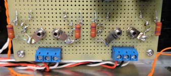
My bias mods based on circuit shown in post #20. See attached pictures.
470 ohm, 1 watt resistor (x4)
1000 ohm, 1/2 watt resistor (x4)
10 ohm, 1/4 watt 1% resistor (x4)
10K, 1/2 watt trimmer pot, Vishay or similar
The cathode bypass caps are left on the main PC board (red caps seen in picture)
Wires from nominal cathode resistor locations on PC board are run out to a generic perf board where resistors and pots are located.
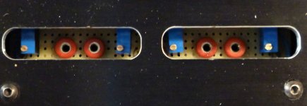
As seen in picture pots and tip jacks for adjusting and measurement can be accessed from slots in the chassis top plate.
An easy mod.
Cheers, Steve
470 ohm, 1 watt resistor (x4)
1000 ohm, 1/2 watt resistor (x4)
10 ohm, 1/4 watt 1% resistor (x4)
10K, 1/2 watt trimmer pot, Vishay or similar
The cathode bypass caps are left on the main PC board (red caps seen in picture)
Wires from nominal cathode resistor locations on PC board are run out to a generic perf board where resistors and pots are located.
As seen in picture pots and tip jacks for adjusting and measurement can be accessed from slots in the chassis top plate.
An easy mod.
Cheers, Steve
Attachments
@ Jacques Antoine .
have you ever worked on or troubleshoot a tube amp?
like you, I had spent my whole life in transistors and I wanted to start a construction but I quickly realized that I did not understand anything, or not as I wanted.
I ended up buying a stereo jukebox amp (Ami-Rowe) to do my learning and it helped me a lot to understand "in real life" and "in theory" and I was able to try several diagrams from this frame .
my two cents from France .
Bonjour Huggygood,
My first tube amp: a learning experience.
I promise I won't poke the live circuit everywhere with bare fingers ⚡⚡⚡
J.
My first tube amp: a learning experience.
I promise I won't poke the live circuit everywhere with bare fingers ⚡⚡⚡
J.
For this reason, I would recommend building the amp as designed without modification. Get it to work first, then mod away if desired. As I learned a long time ago if you include some mods in the initial build and the device does not work as intended, you have no way of knowing if you made a mistake, or one of the mods caused the problem.My first tube amp: a learning experience.
Listen to the amp as built for at least a week with all sorts of different music. Then you can make changes. Start with the feedback compensation cap first as this will make an audible change in the sound, and is dependent primarily on the OPT's characteristics, so it doesn't interact with other mods, except for an OPT upgrade. When modding anything, make ONE change at a time and evaluate it for a week or so before making changes. It is a good idea to keep notes detailing what you like and didn't like about each change. Yes, modding an amp, computer, or music synthesizer kit is work, but ripping out all the mods only to find a mistake, then putting them back one at a time is lots more work, and more likely to cause unintended damage.
I spent some considerable time modding the SPP almost 15 years ago. I never needed the bias adjustment mod, but it is also dependent on the size and quality of the OPT. Most P-P OPT's are tolerant of the minimal imbalance seen in a pair of EL84 tubes unless they are grossly mismatched. Some benefit may be seen with a small conventional or toroidal OPT. I found ways to squeeze 30 watts per channel from good quality EL84's or old 6BQ5's but it requires a 400+ volt supply and an external screen voltage regulator. I wired both channels of this board in parallel to make 50 to 60 watts then used it for a guitar amp without failure.
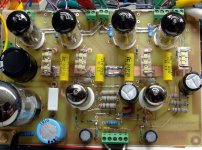
Those who have been around this forum for a while may remember Morgan Jones' Bevois Valley and and SY's Red Light District (RLD) amps. These and the SPP are all very similar designs with a few tweaks. Here is a picture of my WLD version. 4 X camera phone flash LEDs mounted on a heat spreader were used in place of the 270 ohm cathode resistors. This is a pre-production prototype PC board, not the production board being sold. It lit up the room quite well at idle and blinked like crazy when driven 10 dB into clipping with a guitar preamp. The BLD version kept blowing blue LEDS since powerful blue LED's weren't quite perfected in 2008.
Attachments


Perhaps this one ?I have some trouble locating a suitable 230V power transformer: from what I read secondaries should be something like this: 300-0-300@200mA, 6.3V@5A, 5V@3A ?
Cheers,
Jacques
https://www.tube-town.net/ttstore/tt-ma36-36-watt-powertransformer.html
Mona
+1 on the Tube-Town transformer, looks OK. They also have the Hammond 156R choke for 13 Euros that I used in my amps
S.
S.
THE most easily sourced and decent hi-fi amp for a beginner may be (shudder) the Fender AA-Champ. Leave off the first stage and the guitar-centered tone control. A hi-Mu driver into a 6V6 was the peak of domestic players well into the 1950s when it all got cheap. Because the Champ is one of the top five most-built guitar amps, the parts are (in normal times) all available at prices that hurt but are not prohibitive. Get the power transformer for a DeLuxe because it will power two channels of Champ.easy to find transformers and tubes
Thank you all, that gives me a lot of choices for the power transformer.
@ Tubelab : no worries, when it comes to circuits I am a cautious & minimalist kind of builder not the adventurous type.
The same with new cooking recipes 😎
@ Tubelab : no worries, when it comes to circuits I am a cautious & minimalist kind of builder not the adventurous type.
The same with new cooking recipes 😎
I agree with PRR, the best way to have good output transformers is to hunt the wreckage of quality amps from real builders that are several years old, and you can find them, you just have to be patient and on the lookout (I bought 7 or 8 over 3 or 4 years, all under 200 €) (thorens, scott, harman, fisher, Ami Rowe)
the tubes are a world apart, either you like it and dive into it, or you don't like it and the adventure ends there.
- Home
- Amplifiers
- Tubes / Valves
- Easy DIY tube amp