Images looking good
Hi your images looking good.
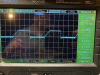
this what a 60hz wave form looks like on the speaker terminals.
Hi your images looking good.
I believe the 2sk117 is defective. If I diode check the n channel FET I am getting 0.69v. Can I sub in a irf540 for testing?
You could probably do it with high value resistors (above 10k) but not with anything much lower. A lot of amps with the 4080 have 470k ohm. I don't remember seeing anything less than that in any amps. I'm sure that the 4080 can drive at least 10k but it's more load than there needs to be for long term operation.

Reduce the input level.
Where is ground?
It looks like the scope is set to DC coupling. Is that correct?
Is the probe set to 1x or 10x?
When you post the next waveform, post one of the DC voltage on pin 4 of IC2.
Where is ground?
It looks like the scope is set to DC coupling. Is that correct?
Is the probe set to 1x or 10x?
When you post the next waveform, post one of the DC voltage on pin 4 of IC2.
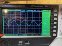
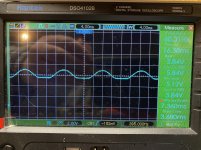
I made a mistake perry. I have full 60hz sine wave on pin 8 of ic2 and on pin 7 of the 4080 I on log have half of the wave form. Could this be because I sub-d in a irf540 in the place of the k117

Q3 was a jfet, not an enhancement mode FET. Just leave it out.
Set the scope to 2ms, 5v/div, set the cursor to the center reference and set the coupling to DC. Post a scope cap of pins 4 and 11 if IC2
Set the scope to 2ms, 5v/div, set the cursor to the center reference and set the coupling to DC. Post a scope cap of pins 4 and 11 if IC2
Really? That explains it, google searches it and found it to be a N-channel FET. It reads almost dead short from 2 outer legs both ways with food check.
- Home
- General Interest
- Car Audio
- earthquake 200dhc-mark2