Did you replace the first power supply resistor with the choke? Or put the choke in front of that original resistor in series?My voltages are higher than what I have seen on others, my B+ input voltage is 300vdc
I would try in series first, that way you maintain the appropriate voltage. If you remove that resistor altogether, you need to bump up another resistor in the B+ supply.
@jayme I did replace the resistor with the choke. I was thinking and was remembering about the Zener diode and how they are are used in this regulation circuit, so I went back and doubled checked and found my mistake. I don't know how I did this but I put the wrong Zeners in the wrong places, IN5373 in place of the IN5374's and the IN5374's in place of the IN5373. Don't know if this makes a difference since they are all added up together to set the 285VDC.
"Did you replace the first power supply resistor with the choke? Or put the choke in front of that original resistor in series?"
Other's have said to remove the resistor and the EAR 834P Clone even shows no resistor only the Choke in that spot.
I also replaced the main rectifier diodes with the MUR400E
Did you replace the first power supply resistor with the choke? Or put the choke in front of that original resistor in series?
I would try in series first, that way you maintain the appropriate voltage. If you remove that resistor altogether, you need to bump up another resistor in the B+ supply.
Tomorrow, I will measure all the Zener Diodes to make sure none are too high. I can always just add a smaller Zener to adjust the set voltage of the regulator. I will report back tomorrow what I find.
Today I went and checked the Zeners diodes in that ladder and all were on the high end right at the limits and one was over it's limit. The total extra volts was 13Vdc and that is putting the output voltage from the regulator @ 299 Vdc. The one Zener 1N5374B was measuring 80 Vdc and it's max is 78.75Vdc per the Datasheet. So I was already prepared and had ordered the new Zener diodes last night and should be here on Friday so I can finish with the power supply and put the EAR 834P clone back into the system and let it break in.
The good thing nothing blew up or smoked! 🙂 So this was the only issue and really wasn't that bad just slightly out of tolerance on the Zeners.
The good thing nothing blew up or smoked! 🙂 So this was the only issue and really wasn't that bad just slightly out of tolerance on the Zeners.
Last edited:
I just measured mine. Here is what I'm getting:Plates Voltages are:
V1 95Vdc
V2 125vdc
V3 297vdc
Plates Voltages are:
V1 93v
V2 117v
V3 297v
B+ 300v
I only gave it a few minutes to warm so it wasn't really stable yet but the voltages should only drift a bit from here. I'm using a bucking transformer so I'm feeding it 115vac. I didn't really check but I'm pretty sure that the 300v supply didn't change when I replaced the resistor with a choke.
What concerns me (a bit) is that the right channel side of tubes 2 and 3 are running a bit lower -- 116v and 90v. Tubes 1 and 2 came out of the phono section of my old Van Alstine mod PAS preamp. The tubes are labeled Penta Labs Made in PRC. I don't remember where I got them but I'm pretty sure that I paid for matched sides. Perhaps I should check the values of some of the resistors.
I have pulled this thing out of the system to replace the diodes with the ultra fast ones that I received. I have to admit that I don't understand what this change is supposed to improve and how. I think that I'm going to put it back into the system and listen to it with the new interconnect cables that I received today!
Pete
I'm not entirely sure how to go about checking these. The voltages in my unit seem so close to what you are seeing.Today I went and checked the Zeners diodes in that ladder and all were on the high end right at the limits and one was over it's limit.
I too have removed the resistor and replaced it with a choke. I thought that the effective impedance of the choke was equivalent to the resistor that it replaces.
Pete
Yes, your measurements are almost exact as mine. It's the Zener diodes set the voltage for the B+ lines. after the input and 2k resistors its the resistors that carry the rest to the plates and are not exact and vary some.I just measured mine. Here is what I'm getting:
Plates Voltages are:
V1 93v
V2 117v
V3 297v
B+ 300v
I only gave it a few minutes to warm so it wasn't really stable yet but the voltages should only drift a bit from here. I'm using a bucking transformer so I'm feeding it 115vac. I didn't really check but I'm pretty sure that the 300v supply didn't change when I replaced the resistor with a choke.
What concerns me (a bit) is that the right channel side of tubes 2 and 3 are running a bit lower -- 116v and 90v. Tubes 1 and 2 came out of the phono section of my old Van Alstine mod PAS preamp. The tubes are labeled Penta Labs Made in PRC. I don't remember where I got them but I'm pretty sure that I paid for matched sides. Perhaps I should check the values of some of the resistors.
I have pulled this thing out of the system to replace the diodes with the ultra fast ones that I received. I have to admit that I don't understand what this change is supposed to improve and how. I think that I'm going to put it back into the system and listen to it with the new interconnect cables that I received today!
Pete
You have to measure the Zener Diode while they are on to see what each is at their Breakdown Voltage. I can already see that the Zeners are the cause in your power supply output voltage that it's at 300Vdc. Start from the bottom diode connected to ground and measure across it, then move up to the next diode. You will see the values, you can measure across each diode to find which one is out of spec. Others have had the same issue/s with the input voltage being too high as well. If it turns out to be a 1N5374 that is at the limit, you can put another 1N5373 which has a 68V breakdown to get it closer to the optimum target value of 285Vdc. If its a little higher it wont hurt.
I have a bread board that I can use to string some Zener Diodes to get the proper voltage for the 285Vdc for B+, this way I can select which combo works best together.
I also found on mine that the preamp PCB resistors are slight different so that is why mine voltages on the plates are slightly out. I have already ordered and received my new resistors for the 2K, 20K, and 200k. These are already matched. I will also place a CL-80 for soft start.
I can't wait to get these new parts in the PS so I can close the book on that part of the upgrade and focus on the Preamp PCB next.
Last edited:
Thanks Drummerboy, I appreciate your help.You have to measure the Zener Diode while they are on to see what each is at their Breakdown Voltage
I have checked the voltages across the Zeners and they range from 70v to 80v. It sounds like I should just replace them all.
I'm glad that I have been running this thing with a bucking transformer so I'm feeding it 115vac. If I had plugged it into my 125vac wall outlet bad things could have happened!
Pete
Yeah, that 80Vdc across the 1N5374 is out of tolerance and should be changed. I find it weird that all these diodes measure I the high side right at or either over their limits. That's why I order On Semi for my replacements.
I don't think you would have seen a difference on the preamp B+ input. Mine was pretty steady at 120Vac from the wall before I noticed that I had accident moved the Variac reset it to 115Vac, but I always like to hit the target measurements. I think the operating voltages at the output of the power supply's B+ is 280-300Vdc
I don't think you would have seen a difference on the preamp B+ input. Mine was pretty steady at 120Vac from the wall before I noticed that I had accident moved the Variac reset it to 115Vac, but I always like to hit the target measurements. I think the operating voltages at the output of the power supply's B+ is 280-300Vdc
So, two 1N5374s and two 1N5373s do you think?Yeah, that 80Vdc across the 1N5374 is out of tolerance and should be changed.
Pete
That's what they have on the PCB. I ordered some Zener Diodes from that same series that had 56Vdc breakdown just in case, I never had any issues with On Semi components so they should be in spec. I order 10 of each just in case I have to sort to get that recommended voltage.
My parts I ordered are arriving today and will finish this up today.
My parts I ordered are arriving today and will finish this up today.
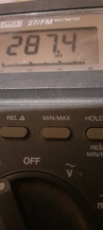
Today I replaced all the Zener Diodes and still it was measuring 298Vdc under load. I removed one of the 1N5374B and put in a 1N5370B which is 56V breakdown., it measured 278.7vdc. So I removed a 1N5374 and put in another 1N5373 and now I have 288Vdc. So now I'm done messing with the B+ voltage.
Now to let it burn in for an hour and put it into the system and see what I get.
Now to let it burn in for an hour and put it into the system and see what I get.
Attachments
Very interesting. I think that I will start by replacing the 1N5374s with the new 1N5373s that I have on order.Today I replaced all the Zener Diodes and still it was measuring 298Vdc under load
Pete
My Power supply has been rock solid at 288Vdc @115VAC input after I took the pic and over an hour on. Even if I raised it to 120Vac it bare moved up 0.5Vdc. I also replace the 2K, 20K, and 200K resistors with Wirewound from Vishay and Ohmite. The 200K was replaced with KOA Metal Oxide, I may have to do that with the 330K resistors. I will go to a local Electronics Surplus and see if they may have some higher resistance Wirewound resistors. These will only be for the B+ supply lines to the tubes.
It's in the system now warming up with my Tube preamp and I will have something to report later tonight. When I receive my TKD pot I will remove the preamp PCB and do the final upgrades and remove those 33uF caps on the pcb. Then I am totally done.
It's in the system now warming up with my Tube preamp and I will have something to report later tonight. When I receive my TKD pot I will remove the preamp PCB and do the final upgrades and remove those 33uF caps on the pcb. Then I am totally done.
I have a similar board, Zero Zone and PSU by them. My regulator on the heaters is at 12.5x which is annoying because 12.6 would be better. It's in spec but I read that 12ax7 go a bit lower under load. You being above 6.3 is probably a good thing (if pin9 is connected, otherwise you have half the voltage you need if they're in series like mine, and the thing sounds horrible at wrong heater voltage). I'm wondering if I should just use AC for the heaters with a choke since I have double 6.3 outputs as far as I can tell on transformer. If it's slightly hot that isn't a problem; only risk is buying 12ax7 cheapies earlier.
Mine was built from kit. I have hum but not diagnosed. It was worse before using a star ground between PSU and phono. Another guy put a box around his phono board and it all went away. My signal RCA's aren't star grounded but I could try it some day.
I went with precision RIAA network. The mods for improving bass are stupid. Anyone that thinks this needs bass improvement literally has other stereo/speaker problems. I see no need to use electrolytic capacitors in the 6x spots on the phono. In fact I have no idea why at nearly 300v anyone would give a rats *** about getting to 40uf either... I'm running 4.7uf on each, no problems. Maybe for posterity I'll add additional 4.7uf caps to have "10uf" like the original design of the board. Contemplating the idea of adding a little R to them so they look more like electrolytics since stock is mostly better... but can't really justify that it would do anything much except maybe unload a little noise to the regulator PSU side that is probably way lower impedance for 60hz anyways.
But anyways the sound is great. Your cap choice is your own, those aren't for me. But I can say with intense confidence to get rid of the Elna. Elna is one of the worst sounding parts I've ever used.
There is plenty of bass on this Zero Zone 834P clone and that was stock. I want to replace my caps on the PCB due to a post that those caps are pretty dry inside and wont last long. I put Kemet caps in for the heater supply, and Nichicon in others. I want 105 degree caps for longer lifespan.
After I swapped the coupling caps and added the choke I found that the system sounded wonderful when the music was simple but as it got more complex it would start to get congested.I want to replace my caps on the PCB
I reasoned that those 33uf caps on the phono board are really local reservoirs for each stage rather than additional filtering. I exchanged them for 82uf Nichicons ( 100uf was out of stock) and the loss of focus and clarity that I was hearing is much ameliorated. I've not bothered with the bypass film caps that I got for them yet.
Pete
@ Pete "After I swapped the coupling caps and added the choke I found that the system sounded wonderful when the music was simple but as it got more complex it would start to get congested."
Those coupling caps will change after so many hours of playing like I mentioned before. I have used these caps in a few upgrades and that's what happened every time. You can't just replace them and expected them to at their best right off the bat.
"I have zero problems with complicated music and I'm running 4.7uf films..."
@Destroyer when the EAR was in stock form I had issues with it and complicated music, not crazy but could hear it. Now after the changes there is no issue at all. I tribute that more to the power supply changes. A Lot of the slight tizziness I was getting is all now gone and I can heard more in between the instruments. The biggest I notice was the noise floor was way down than in stock mode. To the point I thought I didn't turn up the VC after I put the needle down on the record.
All systems are different and they will respond differently to changes. I'm glad everyone is enjoying their EAR 834P Clones after their changes! Enjoy the music Everyone!
Yes, the coupling caps are still gradually improving but the improvements from the 82uf caps was immediate. The settling in of the coupling caps is noticable overall, no matter how much the music is asking of the system. I'm hearing a gradual increase in clarity and focus. The other upgrade is only apparent when there's a lot of stuff going on.Those coupling caps will change after so many hours of playing like I mentioned before.
Pete
- Home
- Source & Line
- Analogue Source
- EAR834P Project