Well...misunderstandings happens
I hope you fix the problem...as i said..i am not having this overshot at home.
regards,
Carlos
I hope you fix the problem...as i said..i am not having this overshot at home.
regards,
Carlos
.............because i see this at input signal too.........
He has confirmed that the +ve half overshoot is also in the input signal...........i am not having this overshot at home.............
That is why I suggested he compare the input and output using his two channel scope.
Yes AndrewT is on the right side.He has confirmed that the +ve half overshoot is also in the input signal.
That is why I suggested he compare the input and output using his two channel scope.
I don't know what happens but this is the first time that happens with this test configuration .
Generators output is ok without any overshoot but when connected to amplifier input then overshoot (oscillation)? apears.
It seems like ground loop.
Dear Carlos this is a diy forum ,these troubles isn't unknown even in factory designers.
Murphy's rules "Anything that can possibly go wrong, does"
Thanks AndewT
Thanks Carlos.
Thimios.
For what it's worth. I had a similar experience with my Honey Badger. There was an oscillation on only the positive side of the wave, and when It would start it affected the input signal too. You can see it in one of the pictures in this post. OS seemed to think it was something "sticking" at high output.
Might be worth reading about what he found.
Blessings, Terry
Might be worth reading about what he found.
Blessings, Terry
dx super A
New test.
+/-35V
I idle=10mV/R22=45mA
Voffset=28mV
I LTP=151.8mV/39R=3.8mA
I VAS=1.121V/180R=6.2mA
V OUT=19V RMS just before clipping
R DUMMY=8R
P OUT=45W sinusoidal JUST before clipping.
-3db at 5Hz doun
-3db at 181KHz up
overshot is still here.
I can't upload photos.
I don't know why.
overshot is present on input and output signal if the dummy is connected
overshot is present only in out signal if no load is connected,in this case input signal is absolutely clear.
If other RL (about 5uH4)is used overshot is smaller.
Last edited:
No overshot in any of my amplifiers tested at my home
Several videos shows several waveforms, all them without overshot.
Why this is happening at your home thimios, i cannot know...but for sure is an effect that is happening your place ...not my place.
Over shot if appear i would not release the amplifier this way....so...if was released, then had no errors in waveforms.
See the series of videos of BBC about electricity...the third movie shows an interesting effect... a block of silicon generating naturally waveform...and a fan was obstructing and not obstructing light that was into the silicon block...and there you could see an interference...this is interesting..and reminds me a possible cause of your problem...if your overshot has a frequecy inserted on it..them it may be RFI (Radio Frequency Interference)
Video is here...the third and last of the Electricity series.... see 40:59
http://www.youtube.com/watch?v=MT8yeMzHvKY
regards,
Carlos
Last edited:
dx super A
Thanks for reply dear Carlos.
I want to know if other builders (same pcb and parts values) can shows scopes.
I repeat that in same place with same configuration i had test many amplifiers without any problem in the past
This time i use two generators for comparison .
Results are same.
Unfortunately i can't upload pictures and i don't know why.
Best Recards.
Thimios.
Last edited:
Overshoot of the input squarewave is because the Source is expecting a correctly terminated transmission line as a load.
If your Source is a 50ohm BNC, it expects a 50ohm coax and the far end of the coax to be terminated with 50r. This becomes the input signal loading of the amplifier. 100k here is no good for squarewave testing.
Else the VHF portion of the squarewave sees an incorrect termination and reflects back to the source. This roughly doubles the VHF content relative to the LF (squarewave fundamental) level. You see overshoot on the leading edge.
I can't explain why the leading edge of the -ve half pulse does not show overshoot.
I said 3days ago
If the RF gurus don't like my explanation, please feel free to post a rewording of it, so that all can read and/or understand the correct explanation.
If your Source is a 50ohm BNC, it expects a 50ohm coax and the far end of the coax to be terminated with 50r. This becomes the input signal loading of the amplifier. 100k here is no good for squarewave testing.
Else the VHF portion of the squarewave sees an incorrect termination and reflects back to the source. This roughly doubles the VHF content relative to the LF (squarewave fundamental) level. You see overshoot on the leading edge.
I can't explain why the leading edge of the -ve half pulse does not show overshoot.
I said 3days ago
..............If the overshoot is in the input signal, see if you can use the probe adjustment to trim it out and/or use appropriate loading on the cable to suppress the reflection.
If the RF gurus don't like my explanation, please feel free to post a rewording of it, so that all can read and/or understand the correct explanation.
dx super A
''overshot is present on input and output signal if the dummy is connected
overshot is present only in out signal if no load is connected,in this case input signal is absolutely clear.
Overhot is visible all over frequency width....from 5hz up to 180kz
If other RL (about 5uH4)is used overshot is smaller.
Thanks .
Dear AndrewT has you see this please?Overshoot of the input squarewave is because the Source is expecting a correctly terminated transmission line as a load.
If your Source is a 50ohm BNC, it expects a 50ohm coax and the far end of the coax to be terminated with 50r. This becomes the input signal loading of the amplifier. 100k here is no good for squarewave testing.
Else the VHF portion of the squarewave sees an incorrect termination and reflects back to the source. This roughly doubles the VHF content relative to the LF (squarewave fundamental) level. You see overshoot on the leading edge.
I can't explain why the leading edge of the -ve half pulse does not show overshoot.
I said 3days ago
If the RF gurus don't like my explanation, please feel free to post a rewording of it, so that all can read and/or understand the correct explanation.
''overshot is present on input and output signal if the dummy is connected
overshot is present only in out signal if no load is connected,in this case input signal is absolutely clear.
Overhot is visible all over frequency width....from 5hz up to 180kz
If other RL (about 5uH4)is used overshot is smaller.
Thanks .
Last edited:
Now it's time for test!
+/-22V
20mV Offset Without any macthing.
45mV Idle current.
8R Dummy load.
1(one) pair out transistors. 2sc5200 2sa 1943.
10KHz
20KHz
80KHz
100KHz
16KHz
There is a pulse peak as the last picture show.
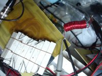
Where is connected that pink 10ohm (think 2W) resistor?
10R/2W pink resistor is connected to 68nf capacitor ,zobel circuit.Where is connected that pink 10ohm (think 2W) resistor?
Thanks .
Last edited:
10R/2W pink resistor is connected to 68nf capacitor ,zobel circuit.
Thanks .
It is ok, but some values on your board are different from original schematic, isn't it?
dx super A
Thanks for interesting.
Thimios.
All values are exactly as silkscreen by vargas pcb except some decoupling capacitors connected direct from power lines to ground which is 120nf instead of 100nf.It is ok, but some values on your board are different from original schematic, isn't it?
Thanks for interesting.
Thimios.
Last edited:
All values are exactly as silkscreen by vargas pcb except some decoupling capacitors connected direct from power lines to ground which is 120nf instead of 100nf.
Thanks for interesting.
Thimios.
How clipping looks like?
dx super A
If drive amplifier with sinusoidal signal up to clip levels ,first clip the negative half if you ask this.
How clipping looks like?
If drive amplifier with sinusoidal signal up to clip levels ,first clip the negative half if you ask this.
Last edited:
If drive amplifier with sinusoidal signal up to clip levels ,first clip the negative half if you ask this.
It is hard to say something without exact schematic.
dx super A
Just now i see for LTP emitter resistor value 33R ,39R,10R ....which is right value?
Thanks.
Thimios.
Dear Carlos can you say where is final schematic for this amplifier?It is hard to say something without exact schematic.
Just now i see for LTP emitter resistor value 33R ,39R,10R ....which is right value?
Thanks.
Thimios.
I use this old set up before Carlos make those final adjustments
R4 82R
R5 39R
R6 39R
R9 68R
R8 68R
correction there is a error image can not be uploaded as soon that is resolve I will upload the image
Regards
Juan
R4 82R
R5 39R
R6 39R
R9 68R
R8 68R
correction there is a error image can not be uploaded as soon that is resolve I will upload the image
Regards
Juan
Last edited:
dx super A
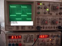
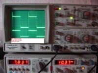
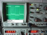
here are pictures with and without load.
Overshot is present from 5Hz up to 180Khz and from 1W to max.
Now i must change emitters resistors in ltp from 39R to 10R and try again.
here are pictures with and without load.
Overshot is present from 5Hz up to 180Khz and from 1W to max.
Now i must change emitters resistors in ltp from 39R to 10R and try again.
Attachments
Last edited:
- Home
- Amplifiers
- Solid State
- Dx Blame ST together Dx Super A