So I need a 12V transformer for the soft start. What about the loudspeaker protection unit. I need:
1) Another transformer
2) Can I use the same transformer that supplies the soft start
3) Can I use the main amplifier transformer
4) At what voltage should this transformer be?
5) A drawing like the previous you send would appreciated.
Suicida,
Yes, you need a 12V transformer for this PCB of the soft start (there were revisions, make sure you have the latest one).
For the loudspeaker protection you're gonna use the AC from the same transformer used on the power supply unit (the main transformer), and also the DC from the output of the power supply unit.
I will make a drawing later.
Somebody of the German Analog-Forum betted with me that his DIY-Amp (SYM...? - I forgot the name)
would sound "better" than my DX BlameES prototype:
I merely sent him a picture of my prototype, will send it to him this weekend.
He is very anxious right now. Will he loose? I am sure.
Best regards - Rudi_Ratlos
would sound "better" than my DX BlameES prototype:
An externally hosted image should be here but it was not working when we last tested it.
I merely sent him a picture of my prototype, will send it to him this weekend.
He is very anxious right now. Will he loose? I am sure.
Best regards - Rudi_Ratlos
The Symassym i have here at my home has more dinamic and more punch in the bass area
But it is lifeless compared to the blame, and the treble is not so good as.
But this is mine one..the second model designed by Michael Bittner...the others, well..these others i cannot say.
regards,
Carlos
But it is lifeless compared to the blame, and the treble is not so good as.
But this is mine one..the second model designed by Michael Bittner...the others, well..these others i cannot say.
regards,
Carlos
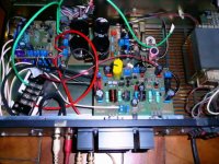
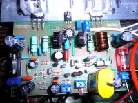
This the wiring diagram for the brazilian kit (soft start not shown, because it's already detailed on the other diagram):
Use the PDF to zoom in. Click on the link below to access PDF high resolution image.
Click here to see it full sized
Use the PDF to zoom in. Click on the link below to access PDF high resolution image.
An externally hosted image should be here but it was not working when we last tested it.
Click here to see it full sized
Great!..this is very helpfull.
Muito bem feito...parabéns..... very well done, congratulations!
regards,
Carlos
Muito bem feito...parabéns..... very well done, congratulations!
regards,
Carlos

Hi,
Can I take a few minutes to explain what is happening with input/output offset?
The base of +IN sits at +49mV.
The base of -IN sits at +53.6mV................
.......................This will reduce output offset of an AC coupled amplifier to very low levels.
Carlos, you have completely misunderstood my intention.For sure we can make this offset zero, also tweaking some resistances then the base ones.
Good both ways... seems to me complementary...or two different ways to result the same...two different roads to go to Rome!
You have interpreted my explanation of how the amplifier works as criticising your methods. That is not my intention.
My intention as stated right at the beginning is to explain to newer Members why we have output offset and what parameters in the amplifier cause this offset.
Take for example the diagram from which I took the voltage readings. It showed a difference of -4.6mV for Vdiff [+IN]-[-IN] and it showed a range of output offset of 0.2V to 10mV.
Having seen the explanation, if a Member reads an output offset of 23mV and then measures Vdiff and finds it is only +-4.6mV, then that Member now knows that there is something wrong with the amplifier. He/she can start seaching for the component or wiring error.
Similarly if output offset is very close to Vdiff then the amplifier is doing what it is designed to do.
If the offset & Vdiff are excessive then he/she needs to find out which components are causing this Vdiff.
As explained it can come from a variety of component tolerances. Resistors values/tolerances, Vbe differences, hFE differences, operating current differences. With an understanding of HOW and WHY the circuit operates, the builder can use this knowledge to check where to look for excessive output offset.
There is nowhere in my explanation where I am criticising your methods.
Negative, i have not perceive your post as criticising my method
I have just explained that we can do the same thing using different methods..just that.
Also i have used the chance you have opened, talking about the subject, to describe my own method to do these things.
I do not think that you are always criticising....just the majority of times, not all times... those last weeks i see you helping, teaching, describing and not only calculating.
Behaving alike a teacher..and a very good one....usually your do not write too much, you just post one or two lines with questions...not answers.
regards,
Carlos
Last edited:
My 2 cents,,The dx Blame amplifer is such a DIY friendly amplifer to build .I can,t see how someone would have problems building this amp..If one follows the directions they would really end up with a great sounding amp, so I,ve been told. Mr Carlos please keep up the great work. Evette
Thank you dear Evette.... we do the best..i hope people suceed
If not, i will be here, with my friends, to support the ones face troubles.
We gonna give them clues to search for mistakes and courage to hunt the bugs.
regards,
Carlos
If not, i will be here, with my friends, to support the ones face troubles.
We gonna give them clues to search for mistakes and courage to hunt the bugs.
regards,
Carlos
Something about capacitors in portuguese language, but you have
down the page, the google translator button.
This was produced by a São Paulo's Radio Amateur (PY2xxxx), a Brazilian, and it is very simple and basic, exactly what we should know and understand.
Other informations, about comparisons, testing using scopes and graphics, if capacitors sounds or not, i will post soon.
This is the Dx Corporation cooperation with you...the basic non unobtanium and inexistium knowledge available, without snake oil and spiritual flúids.
PY2BBS - Hamradio Page
regards,
Carlos
I use to say...also Rudi use to say, the Dx Blame ST and also ES
are the best amplifier we have ever listened.
A direct comparison to Roender amplifier, the one i have assembled and listened too, is very unkind...you can realise what this means.... thinking about the subject and applying basic logic thinking.
Despite of my point of view, supported by many satisfied folks, Roender is an excelent designer, he is my friend, an important person in this forum, that deserves respect and his amplifier, sounds excelent.
He may say the same...inverting brands in the text...i suggest you to first build Roender..and then to build Dx amplifiers....well...i really suggest folks to test, to evaluate by themselves, to compare and to have their own thougths about the subject.
Do not trust designers...they are biased....Roender and me are included in that package..the only way you have to be sure..is building!
regards,
Carlos
Last edited:
I am really not sure how to understand the tone of your post, so let me clarify the question which might have been misunderstood.
If there are people who listened to both FC100 and DX Blame under same conditions (other than respective designers), I would really like to know their subjective opinion on how they compare to each other.
Thanks in advance.
If there are people who listened to both FC100 and DX Blame under same conditions (other than respective designers), I would really like to know their subjective opinion on how they compare to each other.
Thanks in advance.
Tone is hard to detect in written words dear friend
The tone, if you wanna know....is friendly.
regards,
Carlos
The tone, if you wanna know....is friendly.
regards,
Carlos
Hi,
this question was raised in Group Buy.
I have copied it to build.
you can substitute a 4u7F with almost no difference in very low bass output quality and/or quantity.
Using 2u2F may show a slight reduction in low bass quantity. This has F(-1dB)@~14Hz (RC=22ms)
C1=4u7F is a better match to the 220uF NFB cap.
C1=10uF really needs a 330uF or 470uF NFB cap.
this question was raised in Group Buy.
I have copied it to build.
Hi,Originally Posted by supernet View Post
For C1 I will use some good MKP cap, however 10 uF caps are quite big...could C1 be decreased in value without degradation in bass?
you can substitute a 4u7F with almost no difference in very low bass output quality and/or quantity.
Using 2u2F may show a slight reduction in low bass quantity. This has F(-1dB)@~14Hz (RC=22ms)
C1=4u7F is a better match to the 220uF NFB cap.
C1=10uF really needs a 330uF or 470uF NFB cap.
- Status
- Not open for further replies.
- Home
- Amplifiers
- Solid State
- Dx Blame ST - Builder's thread - post pictures, reviews and comments here please.