
Meanman, they are some Omega speakers manufactured here in the states. I've had these for a while now. I use to use them as nearfield monitors for my PC but are now playing in the living room.
The speakers are one of the very first designs by Louis who also became a household name along with Vinnie of RedWineAudio who is known for his battery powered amps a few years ago. [URL="http://www.omegaloudspeakers.com/products/"]http://www.omegaloudspeakers.com
/products/[/URL]
Speakers are all crossoverless full range drivers. Speakers are pretty efficient and sound decent enough. His newer models with hemp drivers sound really good.
Both their products have great system synergy. I used to have one of Vinnie's modded products before he went commercial.
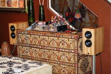
Lovely children, interesting furniture, very nice amplifier
It seems you are from other culture.... looks Mexican i think.
Nice that Hermano.
thank you by the nice pictures.
Speaker looks really good!
Carlos
It seems you are from other culture.... looks Mexican i think.
Nice that Hermano.
thank you by the nice pictures.
Speaker looks really good!
Carlos
Carlos,
Not Mexican, but my mother and father is from Philippines. The "Mexican" is probably because of the strong Spanish blood that runs through our veins. My great,great grandfather was a full Spaniard.
The great furniture is my wife's taste in decor and my 3 year old is actually my daughter. She is a hand-full and a real blessing and we are expecting our 4th child early next year. This Blame will be great for our parties and I'm sure will get the family and friend groovin' and dancin' to the magical sounds.
Nice people from Philiphines...i am glad to know
We have more than 10 guys from Philiphines that have assembled Dx amplifier.
You are very educated folks..your people call us Sir.... this is nice...this means good education, respect, this is always welcome... this open the door to the heart..this creates good friendship...some details, that makes the difference when someone comes to talk with us.
regards,
Carlos
Last edited:
Loudspeaker Protection Circuit & Soft Start
Dear Mitchel,
Thank you very much for your quick response.
Is it possible to describe for me how this circuit works? Why it needs both AC and DC?
Finally I would like to know if the NTC thermistor (R7) from the soft start circuit should be mounted on one of the heatsinks.
Thanks again.
Hello suicida,
It's simple: you are gonna connect the secondaries of your transformer to the AC points on the circuit. Don't connect the center tap, only the two ACs from your transformer.
The DC point on the circuit is connected to the output from your power supply. That is, youre gonna connect the +V and GND from your power supply to the DC ponints on the circuit.
The SW is a thermal switch, and it's optional. If you decide to use one, you shuold use a Normally Open contacts unit (NO type). I think a 70ºC NO thermal switch is fine here. The thermal switch is bolted down to the main heatsink, and it will close contacts once the heatsink reaches the rated temperature of the switch. Once this happens, the circuit will disconnect the loudspeakers, and the heatsink will cool down, because the amp will be unloaded.
If you have any doubts, feel free to ask.
Dear Mitchel,
Thank you very much for your quick response.
Is it possible to describe for me how this circuit works? Why it needs both AC and DC?
Finally I would like to know if the NTC thermistor (R7) from the soft start circuit should be mounted on one of the heatsinks.
Thanks again.
In addition, when you said the transformer you mean the main transformer and the main power supply that is used to supply the amplifier or I need separate transformers (with separate psus) to supply the loudspeaker protection unit and the soft start ? If yes at what voltage and watts?
Thanks
Thanks
Dear Mitchel,
Thank you very much for your quick response.
Is it possible to describe for me how this circuit works? Why it needs both AC and DC?
Finally I would like to know if the NTC thermistor (R7) from the soft start circuit should be mounted on one of the heatsinks.
Thanks again.
the DC supply is the overall power of the circuit and the AC is use to detect when power switch is put OFF. This enable to switch off the relay immediately.
Last edited:
Mitchel may be out to work..but i am sure, as soon as he find time
he will come to answer you dear Suicida.
He is in Rio de Janeiro, time here is -3 GMT, we work from 08:00 AM to 05:00 PM.... our lunch break is one hour long.. reason why we start one hour before the standard nine to five.
regards,
Carlos
he will come to answer you dear Suicida.
He is in Rio de Janeiro, time here is -3 GMT, we work from 08:00 AM to 05:00 PM.... our lunch break is one hour long.. reason why we start one hour before the standard nine to five.
regards,
Carlos
Hi,
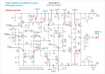
Can I take a few minutes to explain what is happening with input/output offset?
The base of +IN sits at +49mV.
The base of -IN sits at +53.6mV.
as in all feedback amplifiers, the amplifier adjusts the output through the feedback in an attempt to reduce the difference between +IN & -IN to near zero. In this case the Vdiff is -4.6mV
That's as close as this amplifier can get to zero Vdiff. This input voltage offset is multiplied by the DC voltage gain of the amplifier and the result is sent to the output.
DC gain = 1, therefore -4.6mV appears at the amplifier output.
Why do we measure those particular +IN & -IN voltages?
The voltage at these inputs is dependant on the current flowing from the base of each input transistor and the value of the effective resistance to ground for that current to flow though.
If the resistances on the two inputs are the same then the remaining input offset voltage is due to input offset current.
Input offset current is due to the difference in base currents from the two inputs.
Can we as builders of discrete amplifiers do anything about reducing input offset current?
YES, we can.
Firstly, if the two transistors are selected to have similar hFE at the operating current in the circuit then the base current is equal to Ic1/hFE and Ic2/hFE.
Secondly, we reduce the difference between Ic1 and Ic2 currents?
We do this by selecting transistors that have the same Vbe at the operating current of the amplifier.
Matching Vbe and hFE and R of base inputs results in a set up that has low input offset drift with temperature. This can be improved as well. Thermally couple the two input transistors. Now we have Tc~equal and this results in Tj~equal.
Summarising.
Select a pair of transistors that flow the same Ic when their base emitter voltages are exactly the same.
Select a pair of transistors that have +-5% hFE when Ic is flowing.
Select same resistances for the +IN and -IN.
This will reduce output offset of an AC coupled amplifier to very low levels.
Last edited:
suicida said:Finally I would like to know if the NTC thermistor (R7) from the soft start circuit should be mounted on one of the heatsinks.
Hello Suicida.
coolet has already written about your first doubt, so here I go to answer this one:
The thermistor is mounted on the board, not on the heatsink. Here's the drawing that shows how to use the soft start and how to switch everything:
An externally hosted image should be here but it was not working when we last tested it.
Click Here For a Full Sized Image
Translation on some portuguese words used:
- Tomada = socket
- Transformador = transformer
- Chave = switch
Last edited:
Thank you Andrew T.... nice explanation, very clear and helpfull
For sure we can make this offset zero, also tweaking some resistances then the base ones.
I also suggest, to complete your explanation, to people to listen both options and to inform here how this ballance or unballance sounded.
I am using different resistances to the base not because an accident... other options where tried, first amplifier had 15K in both differential bases, other options where tried too.
The choice of values, the low input impedance, was not made that way without think about, or without real world experiences.
I do thank you, this is a very huge cooperation, as they will have the chance to make real world experiences and learn by themselves about how these small modifications sounds.
As you like engines too, alike i do, you know what happens, the differences, the power graphic, the rpm versus power, that results i you advance your ignition point in an engine to +5 degrées.... also, in this case, the modification sounds clearly in the exaust tubes... engine behaves entirelly different, noise, vibration, power, fuel consumption and so on..... we tune amplifier too, alike radio frequency analog transmitters.... sometimes we use small trimmers or padders as capacitors to compensation, to listen what happens.... your approach seems acadhemical, extremelly precise and technical, my way to do things is listening and adjusting.
Good both ways... seems to me complementary...or two different ways to result the same...two different roads to go to Rome!
regards,
Carlos
Last edited:
Boys...you see in the nice Nabuco's sketch, that he is using two transformers
Nabuco is Mitchel's family name... a very important family in my country.
We decide, in the brazilian group buy, to use two supplies to enhance channel separation and to reduce influences of one channel to the other..this way, variations of voltage you may have in one supply because of his related power amplifier consumption, will not be "sensed" by the other channel.
This increases audio quality, reduces distortion in high levels of consumption and defines better the sound stage.
Of course, you can make in the most economical way, using only one transformer and only one supply..but for sure, your result will be worse compared to the result you could have using two transformers and two supplies.
The effect is easy audible, when you turn the volume up when using 4 ohms speakers.
This method was not suggested here, to use two transformers and two rectifieres and filters, because we have, as a tradition to make things cheaper... and this started with the Dx amplifier...so... personnel that have built Dx amplifier can use their own supply to power the evoluted Dx Blame... that has a CCS, a current sink and an enhanced VAS only as difference.... it is a normal, and obvious evolution from the Dx amplifier, and already explored before in the HRII and in the Precision 1.... a lovely amplifier designed by Doctor Self and modified by me for sonics.... i was lucky, result great to an amplifier that is almost the same, having different currents in some stages and using the bootstrap in the place of a CCS to the VAS... only this modificationg could bring the amplifier to an alive audio reproduction, that i was feeling sterile while using the CCS (my point of view)
regards,
Carlos
Last edited:
Thank you very much, Miguel, Andrew, for your picture and your explanation!
This is a great help for all DIYers who go for the DX Blame!
Best regards - Rudi_Ratlos
This is a great help for all DIYers who go for the DX Blame!
Best regards - Rudi_Ratlos
Hello Suicida.
coolet has already written about your first doubt, so here I go to answer this one:
The thermistor is mounted on the board, not on the heatsink. Here's the drawing that shows how to use the soft start and how to switch everything:
An externally hosted image should be here but it was not working when we last tested it.
Click Here For a Full Sized Image
Translation on some portuguese words used:
- Tomada = socket
- Transformador = transformer
- Chave = switch
I would like to thank everybody for the help.
So I need a 12V transformer for the soft start. What about the loudspeaker protection unit. I need:
1) Another transformer
2) Can I use the same transformer that supplies the soft start
3) Can I use the main amplifier transformer
4) At what voltage should this transformer be?
5) A drawing like the previous you send would appreciated.
Thank you very much and sorry for the silly questions.
- Status
- Not open for further replies.
- Home
- Amplifiers
- Solid State
- Dx Blame ST - Builder's thread - post pictures, reviews and comments here please.