It sounds find just can't crank it, but then again it's 50w.
My second board is giving me problems, I can't adjust with bias. Negative side of resistor over the 100r resistor is giving me 2.8v and positive side is giving me 1.2v. I'd really like to start looking for the problems but even if I an doing readings with DMM, I don't know what to look for. Does anyone have a troubleshooting guide.....
My second board is giving me problems, I can't adjust with bias. Negative side of resistor over the 100r resistor is giving me 2.8v and positive side is giving me 1.2v. I'd really like to start looking for the problems but even if I an doing readings with DMM, I don't know what to look for. Does anyone have a troubleshooting guide.....
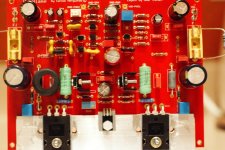
My TX are 25 x 2 After rectification I get about 36v. I have about 18000uf per rail.
What about amps? Minimum 3A, best value around 4A (200VA).
Less than these figures will lead to distortion at high output levels.
it would be unwise to specify/recommend a 200VA 18+18Vac transformer for a 3 or 4A bias single channel ClassA amplifier.What about amps? Minimum 3A, best value around 4A (200VA).
Less than these figures will lead to distortion at high output levels.
If you referring to ClassAB peak current output then that comes from the main capacitor bank.
The transformer simply tops the cap bank back up after the transient has passed.
Last edited:
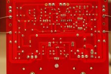
Check emitter resistances dear Wendel...they should be 0.22 ohms
make measurements to be sure the value is this one.
If you have 2,2 ohms (a mistake) then you will have no power, excess of distortion and loss of bass.
Inspect your resistance's values... i cannot do that because some values are not readable in your image..please, send full resolution image to:
carlos.eugenio1951@yahoo.com
Please, measure your power transistors emitter resistance..i know it is written 0.22 ohms there..but give a check, i did found resistances measuring different values than the values written.
regards,
Carlos
Last edited:
That is, how it shall look like!
Nice, simple, effective!
Now connect the input to a secondary winding of your transformer, please.
Best regards - Rudi_Ratlos
Nice, simple, effective!
Now connect the input to a secondary winding of your transformer, please.
Best regards - Rudi_Ratlos
Hello Metal,
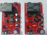
About the LS Protection circuit: it would be best not to use the relay merely to disconnect the amplifier’s output from the speakers. If you simply did this, it’s possible that the contacts would just arc across and so the heavy DC current would continue to flow through the loudspeaker. According to some authors, when you have a heavy DC current and a high DC voltage pushing it along, it can be quite hard to break the circuit. This problem is solved by shorting the NC contacts to the loudspeaker ground lines when the relays turn off. This diverts the arc current to chassis and ensures that the fuses blow on the amplifier.
If the board also has the delayed insertion feature, AndrewT's suggestion to use a 100R resistor between the NC contacts and the loudspeaker ground lines is mandatory, because otherwise you would be shorting the outputs of the amp at start-on.
Mitchel,
the power supply of this LS Protect circuit is driven by the transformer's secondary (!) winding, is then rectified by one (!) diode (right above the AC connector), smoothed by a 330µF cap at the bottom-right side and fed into a 78L24.
When the main's power is switched off, the relay is switched off immediately as well.
Best regards - Rudi_Ratlos
I forgot to ask your permission dear Mitchell
I hope this is a nice surprise to you... your circuit will be used around the world.
regards,
Carlos
I hope this is a nice surprise to you... your circuit will be used around the world.
regards,
Carlos
Hello Carlos,
Actually, this is not the circuit I used for the brazilian group!
The schematic I used is attached below.
View attachment SPKPROT.pdf
Actually, this is not the circuit I used for the brazilian group!
The schematic I used is attached below.
View attachment SPKPROT.pdf
Rudi has been using this LS Protect for a long time, he had never encountered the issues you are assuming dear Mitchel. The protector response is fairly fast, not too fast to cause glitching behavior, and not too slow to cause severe problems on the amplifier side, so the possibility of arc formation is not likely to occur.
Concerning the assumption of shorting the amplifier output, it is not a valid one for this LS Protect, it is impossible. At switch on, the amplifier output is not connected to any thing other than the N.O. relay pin, which it self connected to a high value resistor for the LS protect to sense the amplifier output, this will not cause any shorts, does a resistor that has a value larger than 20K causes shorts for the amplifier output, definitely not.
I have also checked the relay connections, they are correct, terminals of SPK and AMP are open when the relay is OFF.
Last edited:
Hello Carlos,
Actually, this is not the circuit I used for the brazilian group!
The schematic I used is attached below.
View attachment 187714
It might be time to go back to the source.
Silicon Chip Online - 20W Class-A Amplifier Module; Pt.3
We use a lot of these in Australia.
Altronics - Your One Stop Audio Visual & Electronics Supplier
Exactly, it's basically the same as used in SiliconChip's 20W Class A amp, except for the circuit supply, that is a little bit improved, and the fact that it's mono, not stereo. Due to the supply modification, you can use it in any power amp with no need to change any resistors and regardless relays coil resistance.
Last edited:
Exactly, it's basically the same as used in SiliconChip's 20W Class A amp, except for the circuit supply, that is a little bit improved, and the fact that it's mono, not stereo. Due to the supply modification, you can use it in any power amp with no need to change any resistors and regardless relays coil resistance.
...and polar instead of non-polar caps on the low pass filter.
...and polar instead of non-polar caps on the low pass filter.
Correct, but in this case I only did so because of the poor availability of bipolar capacitors here in Brazil - so I used two series caps for each bipolar.
- Status
- Not open for further replies.
- Home
- Amplifiers
- Solid State
- Dx Blame ST - Builder's thread - post pictures, reviews and comments here please.