Carlos, I removed the screw and getting voltages now. Also adjusting the trim pot is working.
What is the screw doing? is it shorting it out? I tested for resistance and was not getting any from Q8 earlier.
Do you suggest that I leave it unscrewed?
Don't want to try to adjust yet to 4.7v since it is not screwed down until you give me ok.
What is the screw doing? is it shorting it out? I tested for resistance and was not getting any from Q8 earlier.
Do you suggest that I leave it unscrewed?
Don't want to try to adjust yet to 4.7v since it is not screwed down until you give me ok.
Attachments
Wendell,
I told you so!
So you have a short between the body (back) of the BD139 and the heatsink (which is grounded in your case).
Please use either a Polyamid M3 screw or an insulating bush.
I wish yoiu success - best regards - Rudi
I told you so!
So you have a short between the body (back) of the BD139 and the heatsink (which is grounded in your case).
Please use either a Polyamid M3 screw or an insulating bush.
I wish yoiu success - best regards - Rudi
Thanks you Carlos and Rudi, you did tell me so but it didn't show up on the resistance test. I'm using a 4/40 screw probably need the bushing or plastic screwdown.
Collet, I built the Blame ES. It is the same board, you have to choose which path you want take ST or ES.
Collet, I built the Blame ES. It is the same board, you have to choose which path you want take ST or ES.
My next project is to build apexaudio's AX-14 amp. I will then compare the two amps and post my feedback here.........
Regards,
Macd😉😉😉😉
U have APEX PSU with protect, do you try short circuit on output (0R22/5W for this power), and do you run amp to the clip level?
Regards
Thanks you Carlos and Rudi, you did tell me so but it didn't show up on the resistance test. I'm using a 4/40 screw probably need the bushing or plastic screwdown.
Collet, I built the Blame ES. It is the same board, you have to choose which path you want take ST or ES.
I see.. thanks wendell. btw for small transistor use 3mm screws.
Regards
Coolet
U have APEX PSU with protect, do you try short circuit on output (0R22/5W for this power), and do you run amp to the clip level?
Regards
Hello Apex......
Yes I did use your psu+protect with my DX. Works perfect.....I changed the components you suggested using +/- 35V. The peak leds works well and when my output goes into clip the protect circuit disconnect the outputs and when I turn the volume a bit down the circuit works well again. I did not test the short circuit protection yet....but I am sure it will work ok....Hope this is okey with you...Sorry for not asking your permission first......I have a second psu+protect pcb that I am planning to use with my NX-14 or AX-14 amp.
Regards,
Macd😀😀😀
Short circuit protect will work with low volume level also, and you no need asking my permission, I share my schematics to be used.
Regards
Short circuit protect will work with low volume level also, and you no need asking my permission, I share my schematics to be used.
Regards
Thanks Apex..... I will test and let you know....I am planning to work on my NX-14 over the weekend....Will let you know on Monday on my progress.....
Regards,
Macd😛😛😛
Hi Rudi,
which dx is wendel using? ST or SE
Regards,
Coolet
Look at my signature, the BoM.
Last edited:
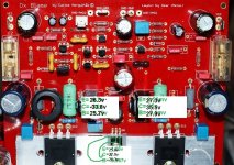
Rudi have suggested you that dear Wendel..he asked you to measure for short
from Q8 colector to the heatsink.
Heatsink is grounded, so, if you have a short there, you put that transistor colector at ground potential that is zero...and zero appeared in your voltage informative image.
Rudi experienced this problem first...he discovered that monthes ago...i have just confirmed his thougths when you pointed zero volts in your image.
this happens from time to time..so, it is an already known problem.
This transistor can be replaced by others, if you want, try a plastic one..almost all NPN transistor will work fine in that position..the bias trimpot setting may variate a little bit but this will be the only problem you gonna face.
regards,
Carlos
The VBE multiplier transistor behaves alike a variable resistance in the circuit
it is there to develop something around 2.125 volts from colector to emitter...and this depends on your setting, your adjustment of stand by current....so...not critical.... must be a transistor and a NPN only....if plastic is better as you will be rid of insulators.
The transistor senses the heat when the heatsink is overheated, this reduces the voltage drop because the junction behaves alike a diode...overheated diodes gives you reduced resistance in the junction and this, of course, as a consequence reduce the voltage drop.
This effect, when heated, reduced the voltage that is biasing the output transistors, and this is the protection we have against overheat.
Different transistor may result different resistance setting in the bias adjustment trimpot, and this is all you will have in real life.
You can use the one you found...measure the unit to be sure it is fine and put it in the BD139 place.
Junk from Panasonic have always these plastic transistors used as voltage regulators...try one of them..... the green ones use to be PNP... try the black ones.
Voltage there is very low...power is also very low.. almost all NPN transistors produced in this world, if Silicon, will work fine.
these transistors are not real plastic made...they have plasticity only. you can give a shape using that material while very hot or without compression.
The Panasonic audio equipment is not a junk audio equipment, i am saying you can find good transistors inside if you can buy a junk, a broken unit.
regards,
Carlos
Attachments
Last edited:
got one amp working it is sounding good but I get some distortion when I try to turn it up, is this a sign the amp is clipping? It doesn't seem that loud, maybe the signal is too hot from my laptop. I will try find another source to play.
got one amp working it is sounding good but I get some distortion when I try to turn it up, is this a sign the amp is clipping? It doesn't seem that loud, maybe the signal is too hot from my laptop. I will try find another source to play.
Start with a low level source. Manage both master and wav levels by clicking on the loudspeaker icon at the bottom right.
got one amp working it is sounding good but I get some distortion when I try to turn it up, is this a sign the amp is clipping? It doesn't seem that loud, maybe the signal is too hot from my laptop. I will try find another source to play.
What transformer are you using?
Meanman is right.
I also noticed poor quality response in high volumes when filters were only 4700uF each rail. Upgrading to 10.000uF fixed this issue.
I also noticed poor quality response in high volumes when filters were only 4700uF each rail. Upgrading to 10.000uF fixed this issue.
The first time I used a 2x24Vac/160Va transformer also had destortion the second time 2x25Vac/160Va.This was a bit better but still not enough.Now I use a 2x28Va/160Va what gives me after rectifying with 4x10000µF a voltage under load(playing music)between min.39 and 42max.Now it plays the stars out of the sky.The next thing I'm gonna try is my regulated PSU with a toroid of 300 or 500Va with a voltage of exact 36Vdc under load.
- Status
- Not open for further replies.
- Home
- Amplifiers
- Solid State
- Dx Blame ST - Builder's thread - post pictures, reviews and comments here please.