I am very happy to tell you that REN received his parcel today.
The Wells Fargo stagecoache has been held up by some Indians for some time, but finally the coachman managed and reached San Reno.
Best regards - Rudi_Ratlos
P.S.: Currently the stagecoach is heading up north, to EVETTE, to Canada. Will take some time, EVETTE.
The Wells Fargo stagecoache has been held up by some Indians for some time, but finally the coachman managed and reached San Reno.
Best regards - Rudi_Ratlos
P.S.: Currently the stagecoach is heading up north, to EVETTE, to Canada. Will take some time, EVETTE.
Last edited:
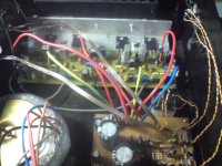
ok, got my blame connected to PSU. + and - coming from PSU to the + and - rail on the Blame. The ground off the blame is connected to the heatsink it is on.
Carlos' video says to adjust the voltage across the resistors in the fuses place to 4.7v. I am getting about 1.8v on one board across the 100r resistor and adjusting the trimpot does not do anything. I connected the other board and getting .555mv across the resistor. Voltage after rectification is about 36v.
What am i doing wrong?
🙁I,m sorry to say but union rules do not allow the stage coach to come this far north😀However I did hear that maybe the pony express might deliver my package🙄
Evette
Evette
Hey guys, Im planning to buy audio grade components to this babe. What components do you recommend to turn it in a real gem?
Thanks!
Thanks!
Wendell...what specific part is wrong i cannot say..but for sure
there is a mistake or several mistakes in your construction.
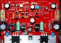
Check it once again.... it seems the error is in the VBE multiplier, the small BD139 transistor circuit, but can be also in the boostrapp resistances..and also in the Vas biasing resistances.
The no adjustment shows clearly that something is wrong... i am unable to inspect your board, as i am distant from you...this is the part of the job that belongs to you.
regards,
Carlos
there is a mistake or several mistakes in your construction.
Check it once again.... it seems the error is in the VBE multiplier, the small BD139 transistor circuit, but can be also in the boostrapp resistances..and also in the Vas biasing resistances.
The no adjustment shows clearly that something is wrong... i am unable to inspect your board, as i am distant from you...this is the part of the job that belongs to you.
regards,
Carlos
Last edited:
Thanks Carlos, I will check! I'm not really sure which section of the board is the "VBE multiplier, the small BD139 transistor circuit, but can be also in the boostrapp resistances..and also in the Vas biasing resistances," I see the 139/140. Is there a way to check if the parts like bd139/140 is working and not dead? Does Checking the voltage across the base to emitter method work for this part?
I think the orientation of parts are correct so maybe it is a dead part.
Tried to post pic but taking forever to upload.
I think the orientation of parts are correct so maybe it is a dead part.
Tried to post pic but taking forever to upload.
Wendell,
did you use washers for the output-transistors and the BDE multiplier - as I told you?
The BDE multiplier consists of the BD139 transistor mounted on the heatsink, the trim-pot, R19 and R20.
Check that there is no connection (infinite resistance) between any of the transistors' legs and the ALU-profile!
This is a common error made.
Did you clean the copperside of the PCB with pure alcohol (no Johnny Walker please - sound will be a little confused afterwards) and a toothbrush to remove the solder-flux? Take a look a the copper side with a magnifying glass then.
I bet you have a short anywhere.
I asked you for a closeup (picture) of your board - both sides please.
Send it to my EMail address.
Best regards - Rudi_Ratlos
@Mario_JR,
go and buy a "highend" soundcard for your PC, something like:
- PCI-Card M-Audio 2496/Delta 410/Delta 44/Delta 66/Delta 1010 etc.
- PCI-Card Audiotrack (with Via Envy24 HT Chips)
- PCI SB Audigy 2 ZS (will do it as well)
and listen to your PC .flac files (via Analog out).
I am sure that you won't miss a "highend" CDP (f.e.).
Best regards - Rudi_Ratlos
DX-ST Complete
Hello Uncle Charlie,
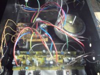
Greetings from South Africa, How is your health doing? I completed my DX Amp last night. I found my initial problem. It was my protection board relay, wrong type. The 2 common points where connected. So when I switch both channels on....the 2 outputs where connected together, so one channel blows while the other one keeps on playing. Fix my problem with two relay's. Works perfect. I posted some pics. I still need to do my final bias current check, clean my amp and fix the wiring a bit.....will do so today......My comment on the sound😀😀😀
Very nice......much better than any commercial amp I listen to.....the bass is solid....the treble is perfect.....you will need very powerful speakers for this amp.....I first used my son's hi-fi speakers with no joy.....I then connected my 2 15inch PA speakers.......and was blown away with the quality of this sound....😱😱😱 This is a very nice amp to build......you will not be disappointed by this amp......it is very solid and the sound is very nice....😛😛😛
Once again......Uncle Charlie has done it again.....😀😀😀 Thanks Uncle Charlie....very nice work......I cannot wait to build my second amp....work will start this weekend.......will keep you posted.......Keep up the good work.....
Regards,
Macd
Hello Uncle Charlie,
Greetings from South Africa, How is your health doing? I completed my DX Amp last night. I found my initial problem. It was my protection board relay, wrong type. The 2 common points where connected. So when I switch both channels on....the 2 outputs where connected together, so one channel blows while the other one keeps on playing. Fix my problem with two relay's. Works perfect. I posted some pics. I still need to do my final bias current check, clean my amp and fix the wiring a bit.....will do so today......My comment on the sound😀😀😀
Very nice......much better than any commercial amp I listen to.....the bass is solid....the treble is perfect.....you will need very powerful speakers for this amp.....I first used my son's hi-fi speakers with no joy.....I then connected my 2 15inch PA speakers.......and was blown away with the quality of this sound....😱😱😱 This is a very nice amp to build......you will not be disappointed by this amp......it is very solid and the sound is very nice....😛😛😛
Once again......Uncle Charlie has done it again.....😀😀😀 Thanks Uncle Charlie....very nice work......I cannot wait to build my second amp....work will start this weekend.......will keep you posted.......Keep up the good work.....
Regards,
Macd
Attachments

DX-ST Complete
My next project is to build apexaudio's AX-14 amp. I will then compare the two amps and post my feedback here.........
Regards,
Macd😉😉😉😉
My next project is to build apexaudio's AX-14 amp. I will then compare the two amps and post my feedback here.........
Regards,
Macd😉😉😉😉
Welcome in the club of DX Blame owners, MACD!
You did a good job! Thank you for the pictures!
I knew in advance that you would like its sound!
Everybody - without exception - likes / loves it!
Best regards - Rudi_Ratlos
You did a good job! Thank you for the pictures!
I knew in advance that you would like its sound!
Everybody - without exception - likes / loves it!
Best regards - Rudi_Ratlos
Thank you MACD, you are very welcome, as usually you build our amplifiers
I am glad you have appreciated in the same ratio we appreciate you.
regards,
Carlos
I am glad you have appreciated in the same ratio we appreciate you.
regards,
Carlos
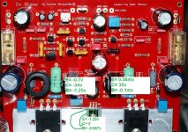
Dear Wendell, the voltage from colector to emitter is around 2.3 volts
depends on the adjustment it can be 2.2 to 2.4 volts....the voltage from base to emitter is around 650 milivolts.
Give a carefull check with calm.... make a copy from the schematic in your printer and go painting parts measured and checked... check transistor positioning, values of resistances and check capacitors for invertion, also diodes.... solder once again the board, clean it and observe if you have shorts.... transistors can be checked while soldered .... resistance cannot be too much low alike a short circuit....if a short is measured, low ohm measurement, then you have a shorted transistor junction... so, check transistor leads with your multimeter in the diode position and check leads, 1-2, 2-3 and 1-3 for shorts.
I wish you good luck, i just cannot be at your side or over your shoulder because the distance we have one related the other, this debugging job should me made by you... i wish i could teletransport..not possible.
regards,
Carlos
Wendell,
start checking the resistances between transistors mounted to the heatsink and the heatsink itself (any short there?), then clean the copperside as I told you.
I wish you success - Rudi_Ratlos
start checking the resistances between transistors mounted to the heatsink and the heatsink itself (any short there?), then clean the copperside as I told you.
I wish you success - Rudi_Ratlos
Try the enhanced image made by Todd Johnson, you can find it in the
Dx Blame ES thread or into Greg Erskine site.... sorry, i have no adress here...i am not using my own computer.
Using the image you may find fast something wrong.
I am feeling sad about your troubles...really i am and i wish you the best in your search for mistakes.
regards,
Carlos
Dx Blame ES thread or into Greg Erskine site.... sorry, i have no adress here...i am not using my own computer.
Using the image you may find fast something wrong.
I am feeling sad about your troubles...really i am and i wish you the best in your search for mistakes.
regards,
Carlos
Try to remove the screw you have fixing Q8 and measure once again dear
Wendell.
regards,
Carlos
Wendell.
regards,
Carlos
I am not at my home dear Wendel, so, the computer i'm using is not mine
and my files are absent here...i have not voltage map..but i have asked the brazilian forum and soon they wake up they will provide me and i will post here to your.
Zero volts at Q8 coletor seems you have a short from this colector to the heatsink that is grounded...so... short to ground because of this screw.... try to remove it to see if things gonna be all rigth.
regards,
Carlos
- Status
- Not open for further replies.
- Home
- Amplifiers
- Solid State
- Dx Blame ST - Builder's thread - post pictures, reviews and comments here please.