Unfortunately cheap chinese multimeter but it measures quite accurate. So it's not it's fault.
Last edited:
Maybe it's showing wrong values? I don't know. So only thing that left me to try amplifier on cheap speaker and see if it's works😉.
Ok. I've connected speaker and there's a problem I have 0,5v offset voltage (when I adjusted it to 5.5v over 100ohm resistor). When I set bigger bias it's getting bigger too. I need help what can be wrong with it?
Last edited:
Check it again...this is not normal
You may have wrong parts on it....for sure you have.
This amplifier had hundreds of guys that build them..and this is not normal..no one has ever reported such a problem....so, check your unit.
regards,
Carlos
You may have wrong parts on it....for sure you have.
This amplifier had hundreds of guys that build them..and this is not normal..no one has ever reported such a problem....so, check your unit.
regards,
Carlos
Possible not to be the end transistors.
I am posting how to install the potentiometer...not because of you Oskar, but because Adi Klausner...and others may like this too.
There are two possible ways, one that helps the amplifier and the other that helps the audio source, the audio amplifier, the signal generator or anything you connect into your power audio amplifier...this style is that helps the audio source not helping the audio power amplifier input as it gonna "see" a variable impedance in it's input.
In this sketch you gonna see that the suggested capacitor value may double related this specific version that is 1uf input.... if your input capacitor has other value, then install two units with almost twice the value suggested.
Capacitor value doubles because we gonna have two in series....or, to keep the original value into the power amplifier, you first must be sure your audio source, pre amplifier or any kind of sound generator does not have DC voltage together the audio AC....if you do not know if it have, or if you do not know how to measure or detect, them install that second capacitor and double the value of both as they gonna be in series with the signal and the final value gonna be the needed one (aproximately 1uF final value)
This is a Dx Super A version, but the style to connect is the same you may apply to your amplifier model, respecting the value of the original capacitor that you must double if you install two...and keep it as the original if you decide to keep just one..the one is already in the audio power amplifier input.
regards,
Carlos
Attachments
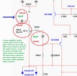
Depending on the amplifier model or version you gonna have different
Values of input capacitors...this also depends on the input impedance.
So, if your model/version uses 10uf in the input audio circuitry, then you have this sketch to be readed.
This kind of potentiometer connection is very standard, and does not help the power amplifier input circuit because it feels a variable impedance connected to the input nodes....other style may help the audio amplifier creating issues to the audio source.
We use this blue arrow capacitor when we do not know if we have DC voltage in the audio source.... if we do not know if the audio source is direct coupled or not...if we do not know how to detect this or how to measure this...it is a safety solution to the ones does not know or have doubts.
It is always better not to use two capacitors..and to keep the original value into the audio power amplifier...but this is another option to the ones does not feel themselves safe to take the risk.
regards,
Carlos
Attachments
Last edited:
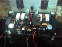
Ok I've just checked values of all elements on my board and unfortunately they are all correct🙁. Only thing that left is zobel near out of the amp. I had problems with soldering coil and I had to ream holes for it. Can that be a problem?
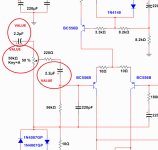
I think i found the problem one bd 139 is broken. But why it broke? I pointed it in the attachment. Does it need heatsink? I read somewhere that heatsink for it isn't required?
I think i found the problem one bd 139 is broken. But why it broke? I pointed it in the attachment. Does it need heatsink? I read somewhere that heatsink for it isn't required?
Attachments
Last edited:
Continue to search for errors..check copper tracks
Capacitor polarity...transistor leads position....this amplifier cannot put out all that DC...this never happened before..so, as a conclusion, you have something wrong on your pcboard.
regards,
Carlos
Capacitor polarity...transistor leads position....this amplifier cannot put out all that DC...this never happened before..so, as a conclusion, you have something wrong on your pcboard.
regards,
Carlos
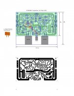
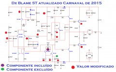
There are hundreds of Dx Blame ST builders in Brazil
They have asked me update.
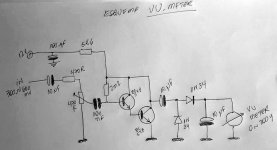
And here you have a video demonstration and the schematic tested.
https://www.youtube.com/watch?v=UnoagUQQxYY
regards,
Carlos
They have asked me update.
And here you have a video demonstration and the schematic tested.
https://www.youtube.com/watch?v=UnoagUQQxYY
regards,
Carlos
Attachments

Here you have a Dx Blame ST, made in Brazil
Sadly the guy tweeter is not fine...harshing....sound is not that way.
https://www.youtube.com/watch?v=SQYtREgrcM8
regards,
Carlos
Sadly the guy tweeter is not fine...harshing....sound is not that way.
https://www.youtube.com/watch?v=SQYtREgrcM8
regards,
Carlos
Something about the speaker used together Dx Blame ST in my living room
There's some comments about a damage that happened with a Dx Blame ST submited to bad use and vibration.
regards,
Carlos
https://www.youtube.com/watch?v=ZJdbPVmw3J8
There's some comments about a damage that happened with a Dx Blame ST submited to bad use and vibration.
regards,
Carlos
https://www.youtube.com/watch?v=ZJdbPVmw3J8
Here you have a Dx Blame ST (left) and a Dx Super A (right)
The transparent upper cover is the Dx Blame ST.....the black one at the rigth is a Brazilian Quasar QA5500, made from 1980 till 1987 and inside there's some Dx Super A modules and a Dx Supply...he may be using the pré amplifier from Quasar in the rigth module.
I am not sure wich module is playing...have to watch VU needles to identify.
Eduardo Silveira, from Ponta Grossa, Paraná - South of Brazil, the one made it.
regards,
Carlos
https://www.youtube.com/watch?v=hn-NOEfOeTU

dx blame st black edition
blame st black pcb🙂
set meter test dc10v adjust 3.5v both rail 100r/2w resistor,sound perfect😀
i figure carbon film 5% is real calculation e24 resistor compare to e96 metal resistor 220r carbon film 221r metal film small increse but big increse when blame st is done haha thanks for da amp
Sadly the guy tweeter is not fine...harshing....sound is not that way.
https://www.youtube.com/watch?v=SQYtREgrcM8
regards,
Carlos
blame st black pcb🙂
set meter test dc10v adjust 3.5v both rail 100r/2w resistor,sound perfect😀
i figure carbon film 5% is real calculation e24 resistor compare to e96 metal resistor 220r carbon film 221r metal film small increse but big increse when blame st is done haha thanks for da amp
Attachments

- Status
- Not open for further replies.
- Home
- Amplifiers
- Solid State
- Dx Blame ST - Builder's thread - post pictures, reviews and comments here please.