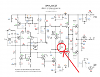
Tested all transistors. Everything is okay. Tryed to power on the amplifier, got a smoke on the BC546 Q6.
I'm completly lost on making this circuit works 🙁
I'm completly lost on making this circuit works 🙁
Tested all transistors. Everything is okay. Tryed to power on the amplifier, got a smoke on the BC546 Q6.
I'm completly lost on making this circuit works 🙁
Did you check Q10? That one could be shorted.
Tested all transistors. Everything is okay. Tryed to power on the amplifier, got a smoke on the BC546 Q6.
I'm completly lost on making this circuit works 🙁
put a 1K resistor between collector and power ground of Q6 it will be protected for overload
put a 1K resistor between collector and power ground of Q6 it will be protected for overload
I would say that, but my DX Blame works fine as is. So, something must be wrong. What about pictures, mod_evil?
I had the same prob with my Blame ST Q6 blew up placed the resistor never had problems again.That resistor doen't harm anything not even the sound but you've a protection instead
I got it HA HA!
Sorry, my workplace isn't clean because just got it and hadn't time to clean it.
The problem in the amplifier was 2 solder joints. It's things that is normal to happen when you make yourself pcb boards and drill them with a sewing needle from your grandma HAHAHAH. (In Brazil things are hard to get almost impossible to find a 1mm drill. Will try to buy it on internet to next time because I will build more 3 amplifiers to my 2.1)
And... I was getting 9v throught the resistor. Adjusted bias and tchram! Everything ok. Didn't tried yet to put sound on it because my bias voltage is increasing by the time, around 0.01v/10s. Is this normal or just heating up?
My heatsink isn't getting hot but I think it's because he is big, even the output transistors aren't getting hot (but the amplifier did't worked for more than 3 minutes) and it's cold now, around 20 degrees outside.
The xformer was made with the EI core from a old nobreak got from trash, remade it 24+24VAC 12A.
This unit is going inside a speaker to make sound on my Beach house with a 12 pol Woofer + Horn will be a lot better than this low cost speakers from China that they sell here around US$200~250.
My DC Offset is 84mV but I think I can get it better adjusting like Carlos told on website.
Is this normal getting this high bias with this normal 160ohm trimpot ajustment to start the amplifier? (I was getting 90mA~100mA and It was getting the smoke on the 100ohm resistor)
An externally hosted image should be here but it was not working when we last tested it.
Sorry, my workplace isn't clean because just got it and hadn't time to clean it.
The problem in the amplifier was 2 solder joints. It's things that is normal to happen when you make yourself pcb boards and drill them with a sewing needle from your grandma HAHAHAH. (In Brazil things are hard to get almost impossible to find a 1mm drill. Will try to buy it on internet to next time because I will build more 3 amplifiers to my 2.1)
And... I was getting 9v throught the resistor. Adjusted bias and tchram! Everything ok. Didn't tried yet to put sound on it because my bias voltage is increasing by the time, around 0.01v/10s. Is this normal or just heating up?
My heatsink isn't getting hot but I think it's because he is big, even the output transistors aren't getting hot (but the amplifier did't worked for more than 3 minutes) and it's cold now, around 20 degrees outside.
The xformer was made with the EI core from a old nobreak got from trash, remade it 24+24VAC 12A.
This unit is going inside a speaker to make sound on my Beach house with a 12 pol Woofer + Horn will be a lot better than this low cost speakers from China that they sell here around US$200~250.
My DC Offset is 84mV but I think I can get it better adjusting like Carlos told on website.
Is this normal getting this high bias with this normal 160ohm trimpot ajustment to start the amplifier? (I was getting 90mA~100mA and It was getting the smoke on the 100ohm resistor)
And... I forgot! While I was testing the transistors I got Q7 placed incorrectly 180º, so it was the thing that was making the burn of Q6.
Just finished the listening of DX Blame ST.
What a great amplifier! Many thanks for your sharing Mr Carlos.
What a great amplifier! Many thanks for your sharing Mr Carlos.
Carlos,
Many thanks by your Design.
I'm just thinking about making a 2.1 unit with 3 Blame ST. Is it possible to use a 18+18Vac xformer from Ham Amateur power supplies?
Att,
Felipe.
Many thanks by your Design.
I'm just thinking about making a 2.1 unit with 3 Blame ST. Is it possible to use a 18+18Vac xformer from Ham Amateur power supplies?
Att,
Felipe.
Hi. I'm building a dx blame st amp and I've got a question.
I finished PSU for amplifier today. I measured DC voltage and it's 2x 31.2V. Is it enough to power it? I think it should work but I'm asking to be sure 😉.
I finished PSU for amplifier today. I measured DC voltage and it's 2x 31.2V. Is it enough to power it? I think it should work but I'm asking to be sure 😉.
Yes, it is enough
You may need to decrease the resistor that is in series with the bias trimpot to allow you to reach the correct adjustment....maybe...not sure about it... gonna depend on your transistors.
regards,
Carlos
You may need to decrease the resistor that is in series with the bias trimpot to allow you to reach the correct adjustment....maybe...not sure about it... gonna depend on your transistors.
regards,
Carlos
the ratio R19:R20 gives the "multiplier"
2k/470 +1 = 5.255 The output of the Vbe multiplier will be 5.255*Vbe
The minimum Vbias will be when the transistor has a low value of 570mVbe and thus the Vbias could be as low as 2.996V
That is shared between the 4 output devices and the two emitter resistors.
Allow 56mV (28mVre each) leaves 2.94V for the 4 Vbe. i.e ~735mVbe each.
You do not need to turn on the output devices to anywhere near 735mVbe
You do not need to change the 470r resistor in the lower leg of the multiplier.
You can also check that the minimum setting of the Vbe multiplier allows the output devices to be turned off using the same method.
The min Vbias is 2k/[470+500]+1 = 3.06 *Vbe But this time one must assume a Vbe at maximum tolerance, try using 650mVbe
The minimum Vbias is 3.06*650 = 1.99V
For the output devices to be OFF the Vbe must be zero.
This time the Two Driver Vbe must be approximately = or more than the min Vbias.
the driver bias will be ~ 550mVbe for the outputs to be off.
The min Vbias should be < 2*550 < 1.1V
But min Vbias is 1.99V.
You cannot turn the output bias OFF.
The VR selected @ 500r is too small. Use a 1k VR, or accept that at first switch on the output could be biased ON.
This is a decision you must make ! either change the VR or accept the output could be biased ON.
Just decrease if if you really need.
Increase it or decrease that resistor depending your needs.
First try with the original values that may fit.
regards,
Carlos
Increase it or decrease that resistor depending your needs.
First try with the original values that may fit.
regards,
Carlos
I'll first try original values and if it not fit I will decrease r20. Thanks for help.
Regards Oskar
Regards Oskar
Or increase it...depending your results.
Be happy....this amplifier is great!...i am sure you gonna dance so happy you gonna be.
regards,
Carlos
Be happy....this amplifier is great!...i am sure you gonna dance so happy you gonna be.
regards,
Carlos
For now I'm happy to say that original values fits perfect😀! I adjusted it with this side Greg's Web Site to 5.17v. So it fits in norm. Strangely I have almost no off set? It ranges from 0,03 to 0,08mv?Be happy....this amplifier is great!...i am sure you gonna dance so happy you gonna be.
regards,
Carlos
- Status
- Not open for further replies.
- Home
- Amplifiers
- Solid State
- Dx Blame ST - Builder's thread - post pictures, reviews and comments here please.