This my map for Dx Blame ST
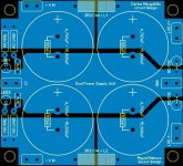
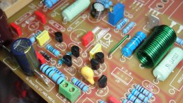
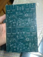
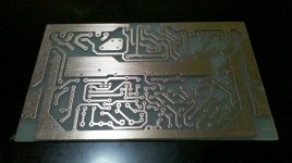
I'm getting ready for ST I made like a map to see how it look if I have an error please be free to correct me I don't mind at all. plus 😀 this really confuse me sometimes but here is a PDF file of my map for ST. I also later I'm going to order not now but the power supply boards, here is the picture of my first board inspire from Miguel Nabuco.
Regards
vargasmongo3435
Attachments
Last edited:
One amplifier, from my Dx amplifiers colection, sounds much better
It is a Dx Blame ST made using original Todd Johnson pcboards...he made the layout for us.
The unit reproduces a little bit more clear sound...more treble, less distortion and more dinamics...also a nice deep bass.....there is some difference in performance compared to other models.... but it has slightly more noise.... with your ears into the tweeter you perceive something even with the input shorted.
I do think the reason why is the use of BC546/556 transistors, also BD139 for VAS and the pair BD139/140 for drivers.
The circuit is almost the same...the input condenser is constituted by 2 units of 22uf/16 volts...i do think the small insulating voltage also play a roll in that stuff too (search for theories about electrolitic condensers operational voltage).
Also the output transistor is different..you can see in this video:
This Dx Blame ST is the one sounds better - YouTube
regards,
Carlos
Found and error on my drawings
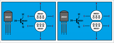
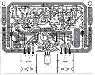
I was checking the orientation of the 2N5401 and BC556 and in my first drawings I made a mistake, so I use the data base information website of the components and fix it here are the illustrations 😉 "my bad" I didn't see it but after you turn the components 180 degree you don't realize things so I made a drawings to see how they look from top view of the PCB board here is.
Regards
Juan
Attachments
Thank you Vargas..... a good help you correcting the stuff
I suggest Dx builders to try if they are using power supplies from 30 to 42 volts only.
Other models with higher voltage supplies should use 2Nxxxx and MJxxxx transistors.
regards,
Carlos
I suggest Dx builders to try if they are using power supplies from 30 to 42 volts only.
Other models with higher voltage supplies should use 2Nxxxx and MJxxxx transistors.
regards,
Carlos
They are old, cheap, awfull, ridiculous transistors
Made of plastic...i you touch the case with the soldering iron the damn thing melts.... a shame.... i hate the way they make these transistors.
But the sound..... well... the sound makes me accept it is awfull, old, cheap, made of plastic, ridiculous and a shame.
I am not sure if the sound is really because of them...because of capacitances, internal construction and specifications...i do think they match with the currents and voltages perfectly....maybe reason are both.... as i said...i am trying to figure out these reasons... a real mistery to me.
Video link into the signature line will send you to a video about it.... a bad video, a terrible audio, but a good suggestion for you...give it a try and tell me what you have perceived.
regards,
Carlos
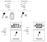
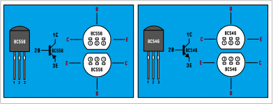
Good Juan!.....be aware folks.... these transistors
have different lead position.... the substitution must be made doing the transistor rotation... a 180 degrées....base continues in the center, but emitter and colector are in different position and should be rotated.
So, if you already have 2N5401 and 2N5551 in your circuit, then when replacing by BCs you should rotate considering the previous position.... substitutions from BCs to 2Ns or from 2Ns to BCs must have this rotation.
The active components (input differential and first VAS transistor) should be the ones to replace, the others are auxiliary and will not make any difference in sonics if you replace them.
Second VAS transistor is BD139 and drivers are also BD139/140...matched within 20 percent in gain.... try the output units shown in the video too.... my units gain are around 200 measured using these cheap chinese digital multimeters.... so, it is the gain using the internal meter current and voltage...not exactly the gain you will have with 35 volts and the working current..it is just a reference to you..not the real thing...if you measure with these cheap multimeters, then you should measure around 200 of gain. (plus 20 percent or minus 20 percent as everything in analogue electronics and electricity)
This amplifier (shown in the video) was always better in sonics..... and the difference in quality you can perceive if you listen one and other..... if you never made the comparison..then you will never know the difference.
regards,
Carlos
Last edited:
Dear DX,
At last I found the energy again and the time to pay my debt to you, Rudi and Metal and build the DX Blame 🙂
A couple of questions, as I buy the rest of the BOM:
1) Does the Zobel network resistance need to be 5W?
2) Can I put the resistor and coil from the speaker output nearer the speaker connector, instead of on the PCB, with the coil mounted around the resistor?
It's hard to get these big R. Maybe I'll build my own 0R22 non-inductive/non magnetic 😎
First I will be a chicken and build the stable ST...then I will get reckless and buid the ES, with separated supplies for the front stage and all the tricks I know for the PS.
Wish me luck.
M.
Zobel is there "just in case"..usually, to home use, it is useless
So, you can put whatever you want if your speaker wires are short (less than 5 meters) and if you are not nearby a strong Radio transmitter...less than 100 meters and 100 kilowatts of power.
Yes, you can put it nearest the speaker connector, you can also split it in two parts, one at the pcboard and other at the speaker terminals...this network is there just in case..... you can even supress them substituting with a wire (the coil).
Non magnetic, special resistors, big magic ones does not make any difference..even if you replace with other values...reduce it instead to increase it will be much better...you can install the ones you have...if you have not, them use a wire instead the resistor.
It is there only to local feedback, we are not collecting voltage into these emitter resistor's extremes to trigger V/I circuits (gladly i do not use these ******* things)... this way.... do not worry too much about it...just do not increase the ones..because it is in series with the audio output.... and any resistance in series with the speaker destroys the bass performance.
To be a chicken is a good thing.... the trouble is if you have an adult male **** around.
hehehehehe...will need to put the back bumpers against some wall for protection.
regards,
Carlos
Zobel is there "just in case"..usually, to home use, it is useless
So, you can put whatever you want if your speaker wires are short (less than 5 meters) and if you are not nearby a strong Radio transmitter...less than 100 meters and 100 kilowatts of power.
Yes, you can put it nearest the speaker connector, you can also split it in two parts, one at the pcboard and other at the speaker terminals...this network is there just in case..... you can even supress them substituting with a wire (the coil).... this filter also helps related the speaker crossover that is reactive..but his is more academic than real in my point of view... i mean...usually this effect does not appear in real world.
Non magnetic, special resistors, big magic ones does not make any difference..even if you replace with other values...reduce it instead to increase it will be much better...you can install the ones you have...if you have not, them use a wire instead the resistor.
It is there only to local feedback, we are not collecting voltage into these emitter resistor's extremes to trigger V/I circuits (gladly i do not use these strange things)... this way.... do not worry too much about it...just do not increase the ones..because it is in series with the audio output.... and any resistance in series with the speaker destroys the bass performance.
To be a chicken is a good thing.... the trouble is if you have a male around.
hehehehehe...will need to put the back bumpers against some wall for protection.
regards,
Carlos
Last edited:

The third brazilian group buy orders are now being shipped
126 kits produced, including Audio amplifier pcboard, Supply pcboard, Speaker protector pcboard and delayed insertion pcboard (surge protection).
Zimmer had started because his will to try the Dx Super A without the need to make modifications in his already built amplifier, then he decided to make an entire new one including the Dx Super A circuit (JVC Super A modified by Brazilian Gradiente and adapted by uncle charlie)*
I am glad people are still interested in this amplifier, the most sucessfull Dr. Self project (my opinion considering the units he made, the ones i could listen and test) tuned by ears by myself... some minor modifications that for sure sounded very good.... some modifications would not be entirelly approved by Dr. Self, as i have forced some parts nearby the limit, a non standard solution....Almost all ammount of credit must go to Dr. Self, at the end he created the Blameless design, i have just tweaked.... so, if you understand the amplifier alike a lovely Rolls Royce, uncle charlie made a polish with some wax on it.... and it continues to be a Rolls Royce.
So, now a days, almost 350 kits provided (not 100% sure about this quantity), the majority in Brazil, and some more 70 kits made by home etching by folks that belong to our diyaudio forum.
There are several pirate's producers in Brazil, USA, UK and China....so, i cannot have account of these ones because they are not under my control but i could detect their presence in Ebay and in some other equivalent sites.
I have to thank you all by the confidence and support, it is nice, now older than 60 years old, i can see i could left a nice contribution to all of us....i am now too much busy to take care of amplifiers... i have 3 to 4 years more, working, before the retirement.
Brazil will finally have Spanish language television channels being received in our country.... this is a result of my actions and i am glad we are not only learning English, but also our neighbor's language, as we are surrounded by spanish language people..finally we are getting that, making stronger relations to create a solid block of countries working in close cooperation and able to communicate 100%.
Pictures taken by cell phone... sorry by that.
* Dx Super A and all Dx amplifiers published in this forum, also several videos posted in Youtube.
regards,
Carlos
Attachments
Last edited:
The one made the first pcboard layout that referenced all sequence
Was Todd Johnson (TAJ)...he made the design, next units produced where developments, small modifications made with the intention to improve..some resulted good, others not that good.
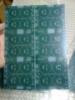
Brazilian green board was made by Miguel Nabuco (Mitchel), also the Supercharged blue boards, the multimodel pcboard.
The credit to be the one have created the pcboard goes to Todd Johnson, and my sincere thanks goes to several other guys that improved (Metal, Rudi,Juan Vargas, Mitchel and some others)
regards,
Carlos
Was Todd Johnson (TAJ)...he made the design, next units produced where developments, small modifications made with the intention to improve..some resulted good, others not that good.
Brazilian green board was made by Miguel Nabuco (Mitchel), also the Supercharged blue boards, the multimodel pcboard.
The credit to be the one have created the pcboard goes to Todd Johnson, and my sincere thanks goes to several other guys that improved (Metal, Rudi,Juan Vargas, Mitchel and some others)
regards,
Carlos
Attachments

Last edited:
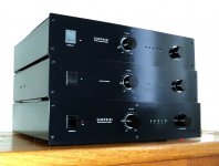
Some more pictures to refresh your memory and to recall reminds to the ones
Belong to the Corporation (the ones have assembled Dx units)
You have the picture from Mitchel (Miguel Nabuco), now a very honored Petrobras men, he passed into tests to work for Petrobrás, the winner in between hundreds of thousands other guys.
Congratulations Nabuco!
regards,
Carlos
Belong to the Corporation (the ones have assembled Dx units)
You have the picture from Mitchel (Miguel Nabuco), now a very honored Petrobras men, he passed into tests to work for Petrobrás, the winner in between hundreds of thousands other guys.
Congratulations Nabuco!
regards,
Carlos
Attachments


Last edited:
Well friends... wife in in Boston, spending uncle charlie
savings.
Build a Dx amplifier folks, despite will not help me about my bank account, will make me less mad about my bank account.... will make me perceive that money is not all that matters in our life.
regards,
Carlos
savings.
Build a Dx amplifier folks, despite will not help me about my bank account, will make me less mad about my bank account.... will make me perceive that money is not all that matters in our life.
regards,
Carlos
Attachments

Last edited:
Hello my good friend Charlie!
Thank you very much for your kind words. It was a pleasure working with you on those projects. We get a long very well, and we seem to have similar points of view regarding PCB layout.
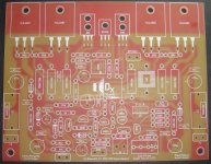
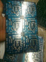
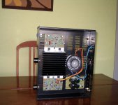
I am slowly going back to electronics, as a hobby, and the DX Blame ST chassis is finally coming to life (I have one with the green boards, but they are not in a nice case). This one is blue boards, and a very nice chassis is being laser cut by a friend.
Thank you very much for your kind words. It was a pleasure working with you on those projects. We get a long very well, and we seem to have similar points of view regarding PCB layout.
I am slowly going back to electronics, as a hobby, and the DX Blame ST chassis is finally coming to life (I have one with the green boards, but they are not in a nice case). This one is blue boards, and a very nice chassis is being laser cut by a friend.
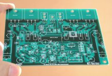
Dx Blame ST Juan Vargas Style
😀 I was bored to death a decide to make a layout from Dx Blame ST and I'm not sure if I got errors but I will check a couple of times. still waiting on parts so I don't have anything else to do, my car is almost done doing body work and it is a really boring Saturday lol well 😉 take care guys!
Regards
Juan
Attachments
Last edited:
Belong to the Corporation (the ones have assembled Dx units)
You have the picture from Mitchel (Miguel Nabuco), now a very honored Petrobras men, he passed into tests to work for Petrobrás, the winner in between hundreds of thousands other guys.
Congratulations Nabuco!
regards,
Carlos
Nabuco look like a really smart guy 😀
Regards
Juan
- Status
- Not open for further replies.
- Home
- Amplifiers
- Solid State
- Dx Blame ST - Builder's thread - post pictures, reviews and comments here please.