Very good Meanman1964 .... are you still dancing?... say, listening
The nice sound will move you to dance.
It is looking great now Meanman.
regards,
Carlos
The nice sound will move you to dance.
It is looking great now Meanman.
regards,
Carlos
What caps should I use for C1? I currently have 2 x 22uf 63v electrolitic Low esr caps installed. I also have available some generic 22uf 100v electrolytics as well as 2 x 10uf non polar audio caps(chinese made)? And also I will be receiving some elna silmic 22uf electrolytics shortly as well. Which of these would be the best choice for me to use as C1 in your circuit Carlos?
The lowest voltage electrolitic condenser you can find
22uF to 16 Volts, and better a 10 volts units....even better if 6 volts units where found by you.
Remove them from portable sets, alike portable tape recorders, portable CD players, or other equipment you may hace as junk...things that operated with low voltage supplies or batteries.
Your input will be less than 2 volts peak to peak...and this gonna be distributed in both series condensers...each one will face no more than one volt peak to peak....there are problems (chemical) when using hundred volts in places you have less than 1 volt...in special the input when DC applied is too much low.
You can use a non polariized unit too, and connecting just one 10uF unit...of course using jumper, because the board was made for two condensers.
In the reality, all options will work...but best sound will happens if you use two 22uF/6 volts units.
regards,
Carlos
My Tri Amp System, Carlos DX Blame ST and Elliot P3A Bridge for the Sub
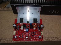
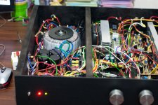
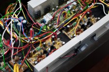
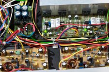
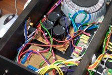
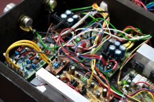
Hello Carlos my friend, this is my completed Amp, its properly DIY even the Casing is Made out of MDF, No noise issues, Dead Silent, I love the sounds of the DX Blame ST, Fantastic, Thanks so much Carlos, here are some pictures.😀
Hello Carlos my friend, this is my completed Amp, its properly DIY even the Casing is Made out of MDF, No noise issues, Dead Silent, I love the sounds of the DX Blame ST, Fantastic, Thanks so much Carlos, here are some pictures.😀
Attachments
Thank you very much Zeraphine....nice pictures
I am glad you are enjoying your amplifier...this makes my day!
Send pictures to the Dx Corporation Headquarters Hall of fame:
carlos.eugenio1951@yahoo.com
And come to be a part of that History...have your pictures there.
regards,
Carlos
I am glad you are enjoying your amplifier...this makes my day!
Send pictures to the Dx Corporation Headquarters Hall of fame:
carlos.eugenio1951@yahoo.com
And come to be a part of that History...have your pictures there.
regards,
Carlos
Update,today I've tested my Blame ST about the sound I'm not planning to tell you yet because I had to test at the wrong place that isn't ideal to do that.
I used a 2x24VAC toroid that gave after rectification 2x34.4VDC
Bias set to 4,3V(pos-rail) and 4,4V(neg-rail)
Offset was 4,5mV when I used an other resistor over R8 it became more instead of less.I also measured 4mV AC.By the way the toroid is 160VA is that enough for one channel
I used a 2x24VAC toroid that gave after rectification 2x34.4VDC
Bias set to 4,3V(pos-rail) and 4,4V(neg-rail)
Offset was 4,5mV when I used an other resistor over R8 it became more instead of less.I also measured 4mV AC.By the way the toroid is 160VA is that enough for one channel
Last edited:
Good...i hope you like...if your body start to move while listening nice music
them the amplifier was aproved.
Created emotions?.... then it is good!
regards,
Carlos
them the amplifier was aproved.
Created emotions?.... then it is good!
regards,
Carlos
No....i just hope it is OK and you like it.
My hope only...i cannot say that in your place.
regards,
Carlos
My hope only...i cannot say that in your place.
regards,
Carlos
I think your transformer will be good enougth...may loose some volts
when operating with 4 ohms loads,but will be very good to 8 ohms loads.....of course if you're using two 160 Watt transformer.
the difference in offset when you compare positive rail to negative rail is also normal.
Your off set is fine too, we should accept till 25 milivolts without the need to reduce it.... this off set means you are having 2.5 microwatts of energy wasted flowing into the load...this is nothing....your result is better than average.
I believe your amplifier is fine, and it will sound fine too, i hope you like it.
regards,
Carlos
I would be very concerned about this measurement.........I also measured 4mV AC...........
How did you take this?
I expect <0.1mVac with the input shorted.
If I get >0.3mVac then I search for problems and solutions, until it is <0.3mVac
Usually when we come with our measurements, it is always useful to describe how we took them. For example, startup staus like after directly turned on, 15 minutes later, input shorted to GND, etc...
Any way, AndrewT, what sort of problem I should be looking for when I measure >0.3mV AC at the output while input shorted to GND?
Any way, AndrewT, what sort of problem I should be looking for when I measure >0.3mV AC at the output while input shorted to GND?
Last edited:
Hi,
first, listen to or measure the frequency of the offending output signal.
Is it pure mains frequency, or double mains frequency, or a buzz based on double mains frequency, or white noise, or pink noise, or varying frequency indicating possible temporary instability, or motorboating, or a rapid switching, or etc.
Depending on that first result will determine your next stage of investigation.
I have another amplifier running infront of me. I measured 4.3mV AC while input is shorted to GND. I thought of what you said before asking you what I should do over here. My Sanwa CD800a measures frequency, and I tried to measure the output frequency with the speaker disconnected, I measured 0 Hz. This doesn't work because the meter needs higher voltage, something like 250mV rms to start counting. May be feeding the meter from an opamp to amplify the output would reveal the frequency, I don't have time for this thought at this exact moment, but this is interesting. Usually this is due to mains ripple in the PSU and amplifier PSRR.
Now, how serious is this measurement AndrewT? Does the amplifier sound very bad when this measurement is violated? Most amplifiers I measured this way are lying between 4 and 5 mV. And non of them oscillate or express bad technical behavior, and those I like to keep up and running, sound very beautifully.
Now, how serious is this measurement AndrewT? Does the amplifier sound very bad when this measurement is violated? Most amplifiers I measured this way are lying between 4 and 5 mV. And non of them oscillate or express bad technical behavior, and those I like to keep up and running, sound very beautifully.
Last edited:
I would be very concerned about this measurement.
How did you take this?
I expect <0.1mVac with the input shorted.
If I get >0.3mVac then I search for problems and solutions, until it is <0.3mVac
I don't have special tools only a multimeter.First I set the bias than I measured the DC-offset without shorted input then switched the meter in AC.What could cause AC voltage on the output?
I don't believe measuring 4mV AC at the output is a problem meanman1964, unless you want to run your amplifier from batteries! Use shielded cases, shielded input and speaker wires, as well as shielded speaker enclosures!
I measured between 3.6mV and 5.3mV AC from many high end amplifiers while their inputs were shorted to GND a year ago. Also in the diy world, I measured 4.1mV AC from LM3886, 4.7mV from STK4191V.
I don't feel what AndrewT said is applicable in the real world!! sq(4mV)/8R resistive load = 0.000002 watt!! should we really care?
So my conclusion is that this is something not to worry about as long as it is as low as I measured it from different amplifiers.
When the input is not shorted, the AC voltage I measured raised to 8mV to 10mV. This is 0.00125 watt, this will burn my speakers! Come on....
Last edited:
this should be 0.0000125 not 0.00125 watt, error in fast calculations! Even with 0.00125 watt, I dun care at all.
I've tested this amp not with the PSU that I'm planning to use unless Carlos says it's OK to use my two 160VA toroids.The mains in my house ain't stable maybe that's the reason for the AC voltage.It dances up and down max. 6 volts not fast but slow.I'm gonna use a special regulated PSU for amps keeps the output voltage rock steady already did this test
Attachments

Last edited:
- Status
- Not open for further replies.
- Home
- Amplifiers
- Solid State
- Dx Blame ST - Builder's thread - post pictures, reviews and comments here please.