Mosfets?.... we are not using dear Wendell.... these Sankens are excellent
You can use them... Rudi and Omar loves them...i love too.
Pictures?... a very good idea Wendell.
regards,
Carlos
You can use them... Rudi and Omar loves them...i love too.
Pictures?... a very good idea Wendell.
regards,
Carlos
Meanman,
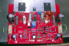
what for are the components indicated by the white arrows?
Best regards - Rudi_Ratlos
what for are the components indicated by the white arrows?
An externally hosted image should be here but it was not working when we last tested it.
Best regards - Rudi_Ratlos
Hi Meanman,
you soldered 2 capacitors over / parallel to the bridges (Is this good English?).
These capacitors are not needed in this place.
They do no harm, since they are short-cut: but please: solder them out.
I do not like the way you soldered the "adjustment-resistors" (beneath, parallel to the fuse).
Please solder them on the solder side of the PCB (below the fuse) and leave them there.
They will be needed only for the adjustment-procedure and will be short-cut once you install the fuse.
Best regards - Rudi_Ratlos
P.S. You use very fine components, but I cannot figure out what type of capacitor you used as the input cap C1.
you soldered 2 capacitors over / parallel to the bridges (Is this good English?).
These capacitors are not needed in this place.
They do no harm, since they are short-cut: but please: solder them out.
I do not like the way you soldered the "adjustment-resistors" (beneath, parallel to the fuse).
Please solder them on the solder side of the PCB (below the fuse) and leave them there.
They will be needed only for the adjustment-procedure and will be short-cut once you install the fuse.
Best regards - Rudi_Ratlos
An externally hosted image should be here but it was not working when we last tested it.
P.S. You use very fine components, but I cannot figure out what type of capacitor you used as the input cap C1.
Alex right these are jumpers that look like resistors.Rudi don't worry the jumper on the signal input isn't soldered.Those points can be used for soldering a MKT cap isn't it?
Maybe those bridges should be surrounded by LEDs, to get some illumination. So they could be seen at night!!!you soldered 2 capacitors over / parallel to the bridges.

I understand, Alex. Thank you.
But these 0 Ohm resistors need not be there.
There are only 2 copper traces on the top side of the PCB - the bridges:
70µM copper traces, coated with gold-rhodium alloy.
Is a 0 Ohm resistor really needed in this place? I doubt this.
Besides: the 0 Ohm resistors do not look good at all.
Rudi_Ratlos
But these 0 Ohm resistors need not be there.
There are only 2 copper traces on the top side of the PCB - the bridges:
An externally hosted image should be here but it was not working when we last tested it.
70µM copper traces, coated with gold-rhodium alloy.
Is a 0 Ohm resistor really needed in this place? I doubt this.
Besides: the 0 Ohm resistors do not look good at all.
Rudi_Ratlos
BTW, I left good space for Q9 and Q10. Both I and Rudi decided that the PCB should be made double sided to use the extra space left behind the jumpers for heatsinks. Q9 and Q10 need good heatsinks. Zero Ohm resistors are not required here.
Yes, Meanman,
you need to solder the input cap C1 (if you have: MKP, MKT, back-to back electrolytes) into the location indicated.
Please do not short it!
This capacitor protects the AMP from DC input-level and acts as a high-pass filter.
Best regards - Rudi_Ratlos
you need to solder the input cap C1 (if you have: MKP, MKT, back-to back electrolytes) into the location indicated.
Please do not short it!
This capacitor protects the AMP from DC input-level and acts as a high-pass filter.
Best regards - Rudi_Ratlos
Last edited:
If meanman is sure his audio source does not have DC in the output
in other words, his audio player having a condenser in the output...then i cannot see problems with the input shorted.
I feel this not pretty, i would be more happy watching condensers or capacitors there and the zero ohms resistance (a short circuit, a jumper that looks alike a resistance to be pretty) can be soldered in the 100N capacitor place..... this gonna short the condensers and the amplifier will continue to look nice.
The jumpers made of zero ohm resistances (jumpers) are not needed but seems will not be a problem...or i could not get the point.
These boards are alike Omar and Rudi baby.... of course they prefere the board is used the way they imagined...... each one of us have our own needs and preferences about the stuff.
I feel much more strange....look no good, one of the drivers are misaligned.
ahahahahahah!
But really.... all these things are really exponential passion applied to electronics...these things, for sure, will not harm the operation and audio quality.
regards,
Carlos
Attachments

Last edited:
You are of course right, Carlos, concerning the necessity of the input cap.
If I am absolutely sure that the input to the DX Blame is already coupled with a capacitor, then of course
I do not need a second one on the PCB.
But how can I be sure about this?
I am trying something new every day.
This is part of the schematics of the Pre-AMP I want to connect to the DX Blame.
The output of the Pre-AMP does not have a capacitor!
I feel safe if I have a DC protective capacitor on the AMP's PCB.
How does the - maybe not needed - on-board capacitor affect the sound?
Best regards - Rudi_Ratlos
If I am absolutely sure that the input to the DX Blame is already coupled with a capacitor, then of course
I do not need a second one on the PCB.
But how can I be sure about this?
I am trying something new every day.
This is part of the schematics of the Pre-AMP I want to connect to the DX Blame.
An externally hosted image should be here but it was not working when we last tested it.
The output of the Pre-AMP does not have a capacitor!
I feel safe if I have a DC protective capacitor on the AMP's PCB.
How does the - maybe not needed - on-board capacitor affect the sound?
Best regards - Rudi_Ratlos
Last edited:
Switch your audio source on and connect your multimeter probe tips
To the output, then adjust your meter to measure DC milivolts.
If you have the coupling condensers, or your output is floating around zero (ground), then you will not measure DC voltage..... no measurement, then you can plug it to your power amplifier without the input condenser...to plug it directly to the input stage base, or it's series resistance.
If you measure some DC..then you gonna need your audio power amplifier input DC blocking condenser or capacitor.
Do not use audio....let your preamplifier in iddle, without amplification, in standby mode..no audio connected to the preamplifier input.
regards,
Carlos
Almost all audio sources are protected..they have output condensers
so, they are safe to you to connect directly to your power amplifier, without the need of audio power amplifier input DC Blocking condenser/capacitor....but you cannot use the volume pot anymore... even knowing that my way to connect is better under that sittuation (fixed resistance to ground), you cannot as you gonna have the potentiometer resistance to ground, and this will be in parallel with the first stage base resistance to ground.
This arrange can be used if you audio source has it's own volume control, and when this volume control is not in the preamplifier output, working as a passive resistive divider...so... you will not control volume in the power amplifier input anymore...you power amplifier will not have volume control, as this control will be at your audio source earlier stages.
regards,
Carlos
Last edited:
Your pré amplifier does not have an output coupling condenser dear Rudi,
but this does not mean you have, or will have, DC in the output.
Sometimes the integrated circuit output has output floating above and below zero volts, .... and this is safe.
You can know switching your pre amplifier on...do not plug any audio in this pre amplifier input connectors, and measure your output connectors...no DC, even milivolts, can be measure there...if you find some milivolts, then you need the input condenser to the power amplifier input and you cannot remove it.
The existance of these two condensers, one in the preamplifier output and other in the power amplifier input, will put them in series..and this will reduce capacitance and you gonna loose deep bass level.
Because of these effects i do not use, do not suggest or support preamplifiers...because power amplifier does not need them.
Each component may cause harm to your sound.... the most simple is usually better..the theory of the "wire with gain"
This small video may help:
http://www.youtube.com/watch?v=ybncYPQSyos
regards,
Carlos
Isn't it so that most pre-amps have a cap on the output? And my cd player has one too.
About those 2 jumpers I'll remove them I didn't know that these were bridges my mistake.
About those 2 jumpers I'll remove them I didn't know that these were bridges my mistake.
Last edited:
This capacitor seems to be the zobel filter capacitor
This one should face 60 volts peak to peak if your amplifier starts to oscilate,
Check it please, if it can face this voltage, and replace it please, for safety reasons, for a 100 volts unit if needed.
If you do not have the correct value, dear Meaman, try another value, giving preference to the voltage and not the capacitance...so, 33N,47N, 56N, 68N, 100N, 150n and 220n can be used
regards,
Carlos
Last edited:
This one should face 60 volts peak to peak if your amplifier starts to oscilate,
Check it please, if it can face this voltage, and replace it please, for safety reasons, for a 100 volts unit if needed.
If you do not have the correct value, dear Meaman, try another value, giving preference to the voltage and not the capacitance...so, 33N,47N, 56N, 68N, 100N, 150n and 220n can be used
regards,
Carlos
Carlos if you mean C23 the green one I use that's a 100V type.
- Status
- Not open for further replies.
- Home
- Amplifiers
- Solid State
- Dx Blame ST - Builder's thread - post pictures, reviews and comments here please.