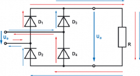
This image shows the wiring...
It should allow you to use your original 12VA transformer 🙂

It should allow you to use your original 12VA transformer 🙂
Last edited:
Hi currentflow,
Thanks for your patience, that you help me to solve this problem with the 7812 regulator and the image.
I'm waiting on email, and post the answer here.
Regards,
Rudy
Thanks for your patience, that you help me to solve this problem with the 7812 regulator and the image.
I'm waiting on email, and post the answer here.
Regards,
Rudy
Hi currentflow,
Thanks for your patience, that you help me to solve this problem with the 7812 regulator and the image.
I'm waiting on email, and post the answer here.
Regards,
Rudy
My pleasure. While you're waiting for that email, please try the diodes (if you have any).
As I see it, your options are:
a) Fit the extra two diodes and possibly increase the values of C1 & C2 to 470uF/25V each, or
b) Use a 12-0-12 transformer, connecting it to all three board terminals.
With half-wave rectification and the relatively low-value smoothing capacitors (2 x 100uF), you're just not getting enough current into the regulator.
Thanks currentflow,
My intention was to 12-0-12 2A ordering, also stood on the board 12-0-12
But vintage_audio_lab told me via email that 12-0 1A was enough for this application, thats the reason why I ordered this 12-0 1A transformer.
When I get no email after this weekend , I order this 12-0-12 2A transformer.
Then I take option B 😉
b) Use a 12-0-12 transformer, connecting it to all three board terminals.
I'm still waiting on email,
Regards,
Rudy
My intention was to 12-0-12 2A ordering, also stood on the board 12-0-12
But vintage_audio_lab told me via email that 12-0 1A was enough for this application, thats the reason why I ordered this 12-0 1A transformer.
Dear Sir:
http://www.okaphone.nl/product/images/212048c.jpg
This transformer is 12-0-12 full wave output.
What you need should be simpler one. Just need to have one 12-0 output, 1A current is quite enough.
Sincerely, Kevin
- vintage_audio_lab
When I get no email after this weekend , I order this 12-0-12 2A transformer.
Then I take option B 😉
b) Use a 12-0-12 transformer, connecting it to all three board terminals.
I'm still waiting on email,
Regards,
Rudy
Thanks currentflow,
When I get no email after this weekend , I order this 12-0-12 2A transformer.
Then I take option B 😉
b) Use a 12-0-12 transformer, connecting it to all three board terminals.
I'm still waiting on email,
Regards,
Rudy
Hi Rudy,
Using option a) will cost less than 1 euro for two diodes and achieve exactly the same result. You would only need to install two diodes on one board and then connect the three power terminals of each board in parallel. This makes the most sense when you have a perfectly good transformer 😉
I tested this module also with 12v 10A torriod , and I have also a voltage drop, how do you explain this?
Sorry I question this, because my electro knowledge does not go as far to understand this 😉
Sorry I have no diodes to test, but I will order diodes.
Regards,
Rudy
Sorry I question this, because my electro knowledge does not go as far to understand this 😉
Sorry I have no diodes to test, but I will order diodes.
Regards,
Rudy
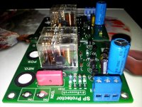
I have searched and found 4 x 1N4007
I have soldered 2x 1N4007, this is the result.
Before speaker protection goes on:
Regulator 7812 input, 17,34v
Regulator 7812 out, 12,10v
Speaker protection goes on:
Regulator 7812 input, 15,10v
Regulator 7812 out, 11,87v
This is much better, you see now a little voltage drop 😕
Regards,
Rudy
I have soldered 2x 1N4007, this is the result.
Before speaker protection goes on:
Regulator 7812 input, 17,34v
Regulator 7812 out, 12,10v
Speaker protection goes on:
Regulator 7812 input, 15,10v
Regulator 7812 out, 11,87v
This is much better, you see now a little voltage drop 😕
Regards,
Rudy
Last edited:
I have searched and found 4 x 1N4007
I have soldered 2x 1N4007, this is the result.
Before speaker protection goes on:
Regulator 7812 input, 17,34v
Regulator 7812 out, 12,10v
Speaker protection goes on:
Regulator 7812 input, 15,10v
Regulator 7812 out, 11,87v
This is much better, you see now a little voltage drop 😕
Regards,
Rudy
This is because before you added the two extra diodes, you had a half-wave rectifier. Capacitors C1 and C2 (both 100uF) only became charged on the positive peaks of the AC input cycle, while the negative peaks were being unused. Their values were too low to maintain the voltage in this way and were discharging faster than they were being charged.
Adding the two extra diodes causes these capacitors to charge on the negative half of the cycle as well as the positive. Therefore the capacitors are now being charged twice as often as before and you now have full-wave rectification. Increasing C1 and C2 to 470uF (25V) would improve the situation even further under load when the relays are on. I hope that makes sense.
I posed this question to vintage_audio_lab,
When you look at this forum, I am busy with the speaker protection module , and measure weird things:
http://www.diyaudio.com/forums/soli...-mkiii-hx-builders-thread-20.html#post2912256
What is the utility of this 7812 regulator in this circuit, I have a voltage drop, with this 7812 regulator.
This is the answer to my question:
Dear Sir:
7812 regulator was used for dc detection and time delay circuit. And relay also need dc supply to drive it.
Sincerely, Kevin
Nothing about voltage drop ...
I thought the proper operation you need to have a stable power supply
currentflow,
Thanks for the explanation, I definitely try 470uF C1 and C2
Regards,
Rudy
I thought the proper operation you need to have a stable power supply
currentflow,
Thanks for the explanation, I definitely try 470uF C1 and C2
Regards,
Rudy
Last edited:
Nothing about voltage drop ...
I thought the proper operation you need to have a stable power supply
currentflow,
Thanks for the explanation, I definitely try 470uF C1 and C2
Regards,
Rudy
Hi Rudy,
Since you'll be using these modules to protect your speakers, it's worth spending a little time to ensure they operate reliably.
Your measured voltage of 15.1V before the regulator when the relays are on is now greater than the minimum required value of 14.5V, which is good news. As we don't know how much ripple is present before the regulator, the changes to C1 and C2 would definitely be beneficial although their values are not critical. You could use 330uF or 470uF with a minimum working voltage of 25V to improve on the results. Select the largest of these values which will comfortably fit on the PCB. Another possibility would be to fit a single 1000uf/25V instead of two capacitors, if there is room.
Hello currentflow,
Thanks for your help, I now have a 1000uF capacitor soldered in there, and the speaker protection module is now stable.
Thanks vintage audio lab for a "good and stable speaker protection module you send me" 😕 🙄
We on this forum do the research to make this a good and stable working speaker protection module
Regards,
Rudy
Attachments
Hello currentflow,
Thanks for your help, I now have a 1000uF capacitor soldered in there, and the speaker protection module is now stable.
Thanks vintage audio lab for a "good and stable speaker protection module you send me" 😕 🙄
We on this forum do the research to make this a good and stable working speaker protection module
Regards,
Rudy
One of the pleasures of DIY is in improving others' designs... 😉 Out of curiosity, what is the voltage before the regulator now that you've changed the capacitors, with the relays on? Over 16V?
Steve
One of the pleasures of DIY is in improving others' designs... 😉 Out of curiosity, what is the voltage before the regulator now that you've changed the capacitors, with the relays on? Over 16V?
Steve
Hi Steve,
Everything is now connected and the speaker protection module works.
Input voltage 7812 regulator with the relay on, is now 16, 67v 😉
Regards,
Rudy
Hi Steve,
Everything is now connected and the speaker protection module works.
Input voltage 7812 regulator with the relay on, is now 16, 67v 😉
Regards,
Rudy
Looks good to me. Now enjoy your Hx!
Steve
Question on gain
Hi everyone, quick question here...
The gain of the Hx amp seems very high compared to "consumer" power amps. Basically, a consumer amp rated at 200W RMS into 8 Ohms will show a gain averaging at around 28x.
Now when I look back at the schematics of the Hx, the gain seems to be around 120x. Am I missing something?
I think Carlos determined that 390Ohm resistor for direct connection to portable devices, hence the huge gain ratio.
Picture showing the two resistors used for calculating the gain:
Attachments
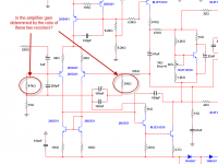
I had similar question in the past and Carlos answered me that I can change the value of the 390R resistor to adjust the gain of the amp.
Also I think that gain is determent by the two resistors in the NFB and not by this in the input to the GND. In this case you are right because they have the same value but keep it in mind.
Regards!
Also I think that gain is determent by the two resistors in the NFB and not by this in the input to the GND. In this case you are right because they have the same value but keep it in mind.
Regards!
- Status
- Not open for further replies.
- Home
- Amplifiers
- Solid State
- Dx Blame MKIII-Hx - Builder's thread