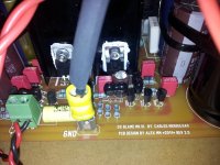
The collectors of those 3 MJE seem to be hardly connected to the heatsink! Or is there a small isolator (dark ring)?
We can't see what you have not photographed.
I and I suspect we, need an overall view.
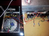
Two red insulated cables/cords for both +ve and -ve supply.
Two blk insulated cables/cords connected to PCB Power Ground and going off pic, in different directions.
I and I suspect we, need an overall view.
Two red insulated cables/cords for both +ve and -ve supply.
Two blk insulated cables/cords connected to PCB Power Ground and going off pic, in different directions.
Last edited:
Rudy, the small black "isolation bushes" (Vigier called them this way) have a tendency to "break", when you fix them. I use Polyamid screws for the TO-220 and TO-126 transistors.
Please measure the resistance between the small transistors' legs and the heatsink.
Rudi
Please measure the resistance between the small transistors' legs and the heatsink.
Rudi
Did you forget the "backend-frontend" GND connection (the resistor on the left side of the green input signal connector)?
Rudi
Rudi
The collectors of those 3 MJE seem to be hardly connected to the heatsink! Or is there a small isolator (dark ring)?
No there is a mica isolator.
Attachments
Did you forget the "backend-frontend" GND connection (the resistor on the left side of the green input signal connector)?
Rudi
Yes, you meen the 10R? I thought it is only necessary if you need a potentiometer direct on the board.
Last edited:
We can't see what you have not photographed.
I and I suspect we, need an overall view.
Two red insulated cables/cords for both +ve and -ve supply.
They are going to the 47000uF elco's
The min -60v is a black shrink hose over it so that I can see that is the min -60v
Two blk insulated cables/cords connected to PCB Power Ground and going off pic, in different directions.
1 black kabel is going to the speaker terminal and the other one is going to the GND copper plate between the elco's.
Regards,
Rudy
Last edited:
No Rudy, a resistor (10 Ohm) or wire is necessary at this location (has to do with lifting up the AMP's GND-plane in correspondence
with SIGNAL GND).
I remember that there was a discussion in the very 1st posts what to use.
I did not follow this discussion to the end, but this resistor may not be left open!
Try a 10 Ohm resistor and measure again!
Rudi
with SIGNAL GND).
I remember that there was a discussion in the very 1st posts what to use.
I did not follow this discussion to the end, but this resistor may not be left open!
Try a 10 Ohm resistor and measure again!
Rudi
Rudi I will try this, It was indeed confusing about this 10R resistance.
Can someone who has the amplifier ready confirm this about 10R resistor?
I use a preamp and the input and output connector is isolated, is this resistance necessary or can I use a wire.
Regards,
Rudy
Can someone who has the amplifier ready confirm this about 10R resistor?
I use a preamp and the input and output connector is isolated, is this resistance necessary or can I use a wire.
Regards,
Rudy
Last edited:
The Main Audio Ground is the reference point for a whole series of other circuits.
Signal Return
Speaker Return
PSU Zero Volts
Chassis
PCB Power Ground
Disconnecting Network, if fitted
You stated earlier that you had located your Main Audio Ground on the Speaker Return Terminal.
That means you must bring all the other reference connections to that same Terminal.
But, which Speaker Return Terminal do you use? Left or Right?
I viewed the video of Carlos, may just be a wire so I solder a wire.
About lifted ground to MKIII-Hx input. - YouTube
Regards,
Rudy
About lifted ground to MKIII-Hx input. - YouTube
Regards,
Rudy
Now I measure, I short the input signal hot to signal ground:
1 mv emitter resistor
37mv DC speaker terminal
0,2mv AC speaker terminal
Regards,
Rudy
1 mv emitter resistor
37mv DC speaker terminal
0,2mv AC speaker terminal
Regards,
Rudy
Last edited:
What is the value of the emitter resistors, what type of output transistors are you using?
Rudi
Rudi
U = R * I
1 mV = 0.47 Ohm x 2.1 mA
The value of 2.1 mA is much too small.
Keep measuring the voltage drop over an emitter resistor and very slowly decrease the trim-potentiometer's value.
Does the voltage that drops over the emitter resistor increase?
Rudi
1 mV = 0.47 Ohm x 2.1 mA
The value of 2.1 mA is much too small.
Keep measuring the voltage drop over an emitter resistor and very slowly decrease the trim-potentiometer's value.
Does the voltage that drops over the emitter resistor increase?
Rudi
When you know that the amplifier is wired correctly, power it up direct on line and then start setting the output bias.
BUT!!!!!
when you remove the 10r bias measurement resistor, the bias will change. Upwards!!!!
BUT!!!!!
when you remove the 10r bias measurement resistor, the bias will change. Upwards!!!!
That's where the shorting link should go, between the signal input and the signal return.Maybe not that important but you've switched the input cable
I power up directly from the mains, and I have the fuse in there.
Andrew you mean the 100R resistor over the fuse, when I remove that resistor I cannot measure the 1mv bias anymore?
If the fuse is in there, then the 100R resistor works anymore, or should I solder out the 100R resistor?
when you remove the 10r bias measurement resistor, the bias will change. Upwards!!!!
Andrew you mean the 100R resistor over the fuse, when I remove that resistor I cannot measure the 1mv bias anymore?
If the fuse is in there, then the 100R resistor works anymore, or should I solder out the 100R resistor?
Last edited:
- Status
- Not open for further replies.
- Home
- Amplifiers
- Solid State
- Dx Blame MKIII-Hx - Builder's thread