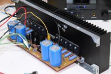
Finally it's done
Testing in progress....Playing music loud and clear.
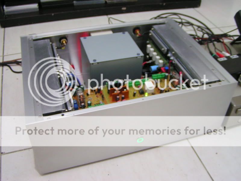
I will post more photos, camera's batt already exhausted.
Testing in progress....Playing music loud and clear.
I will post more photos, camera's batt already exhausted.
Nice really nice
😀 muy bueno se ve brutal tremendo mano! "translation": awesome!😀
Testing in progress....Playing music loud and clear.
I will post more photos, camera's batt already exhausted.
😀 muy bueno se ve brutal tremendo mano! "translation": awesome!😀
@ Rudi, I will definitely make a light bulb tester before I plug in the amplifier.
@ Evette, I appreciate that you've helped me with the components 😉
Regards,
Rudy
@ Evette, I appreciate that you've helped me with the components 😉
Regards,
Rudy
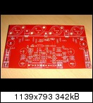
220uF 100 volt 18mm. max 10mm on the board
47uF 100 volt 12mm. max 9mm on the board
I stop now with build because the 100 volt caps do not fit on the board.
I wait or another board is created, or I need to bring the voltage down and buy new transformers.
Regards,
Rudy
47uF 100 volt 12mm. max 9mm on the board
I stop now with build because the 100 volt caps do not fit on the board.
I wait or another board is created, or I need to bring the voltage down and buy new transformers.
Regards,
Rudy
Last edited:
Testing in progress....Playing music loud and clear.
I will post more photos, camera's batt already exhausted.
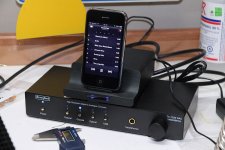
Nice job Junie ... where did you purchase the panel light ?
220uF 100 volt 18mm. max 10mm on the board
47uF 100 volt 12mm. max 9mm on the board
I stop now with build because the 100 volt caps do not fit on the board.
I wait or another board is created, or I need to bring the voltage down and buy new transformers.
Regards,
Rudy
What voltage are you running?
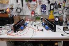
Board 'B' was started tonight. Went silk smooth. Couldn't resist making them sign together in unison.
They're built so identical that all initial readings were exactly the same.
DestroyerX; you were right, the sensivity is a bit on the low side with portable devices, even though I'm using an external DAC with a preamp stage. I may reduce the 390 ohms resistor to 270 or 220 to unleash all the guts this monster is having. I'm gonna do this on a single channel first and compare.
Same for the CCS's resistor. I'm gonna increase from 22 ohms to 47 on one channel to compare the heat dissipation reduction. I will report my findings here. Gimme a few days.
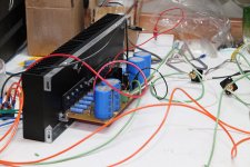
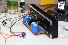
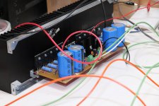
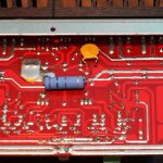
Some pics below. It's a mess of wires for now, I'll work my aesthetics in the enclosure. 😀
They're built so identical that all initial readings were exactly the same.
DestroyerX; you were right, the sensivity is a bit on the low side with portable devices, even though I'm using an external DAC with a preamp stage. I may reduce the 390 ohms resistor to 270 or 220 to unleash all the guts this monster is having. I'm gonna do this on a single channel first and compare.
Same for the CCS's resistor. I'm gonna increase from 22 ohms to 47 on one channel to compare the heat dissipation reduction. I will report my findings here. Gimme a few days.
Some pics below. It's a mess of wires for now, I'll work my aesthetics in the enclosure. 😀
Attachments
What voltage are you running?
My Transformer is 2x 42Vac 2000Va, I have 2 of them.
Andrew wrote,
42Vac, 3to 4% regulation, on a 220/230Vac mains system must operate very close to 63V. I would not run 63Vcaps.
I think you have made the correct choice going for 80Vdc rating.
Regards,
Rudy
Last edited:
Rudi,you could ask Cannonnica how much voltage he has on those caps.My idea is that Alex has a reason for using 63Volt caps there
63 volts caps are not really 63 volts capacitors because manufacturers are not stupid
Everyone knows capacitors goes to power supply (mainly)...also everybody knows that mains supply has a variable voltage .... sometimes variation is 10 percent (plus and minus) and sometimes it is 20 percent (plus and minus)....if you have 20 percent plus, then your 44.5 plus 44.5 AC volts from your transformer secondary, increased in 20 percent will go to 53.4 plus 53.4 VAC ..... if you rectify and filter this will turn 75.29 VDC (multiplied by 1.41 because rectification and filtering)... so, you see the increasing in the voltage and the 63 volts will become 75 volts.... of course manufacturers make electrolitic condensers to face much more than that voltage... they produce reliable things because they do not want to close their doors and bankrupt, as they gonna face a lot of complains and devolution of units.
So, if someone could produce a capacitor insulated to exactly 63 volts... and IF this capacitor worked as a zener (It does not work this way) it will be destroyed when mains voltage increase due to natural variations we have in frequency and in amplitude.
Because of that, manufacturers print the "minimum guaranteed insulating voltage" into the plastic case..but in the reality, it can face at least 30 percent more..in my experience, i tried 60 percent more voltage in several capacitor and they worked fine for years long without leakage, over temperature or short circuit..no looses of capacitance, the case was not inflated and the over voltage rubber cap not broken because of excess of internal pressure in the electrolitic fluid.
To use with 63 volts you should use 63 volts capacitors (condensers) not to spend more money than you need.... more insulation and more capacitance increases size and price....waste o money..overkill.... excessive care....non needed exageration.
People believe they should increase to have guarantee...but the factory have concluded that in advance and did that to you...they have a brain too folks....manufacturers, inside their skull, there's a brain too.
- 63 volts capacitors are perfect to 63 volts supplies and you do not need higher insulating voltage units
- 63 volts capacitors can outstand much more voltage than the voltage printed as minimum guaranteed voltage.
- Also, the capacitance is not the value written, it is more than the value printed...that is the "minimum guaranteed capacitance"
In 50 years i never had a destroyed (pop out) condenser using the "minimum guaranteed voltage" printed into the capacitor plastic cap...and also i never had a unit destroyed because working in a over voltage condition ... I said never happened
If people has money to waste...well.... be happy and try 100 volts because they look bigger.
regards,
Carlos
Last edited:
I think you are wrong to suggest to anyone, least of all the beginners who are attracted to your DX range of amplifiers that manufacturers either by design or accident apply a Factor of Safety of 1.3 to their electrolytic capacitor voltage ratings................. manufacturers print the "minimum guaranteed insulating voltage" into the plastic case..but in the reality, it can face at least 30 percent more..in my experience,
It is upto the designer of the equipment to ensure by thorough testing that the 63Vdc rating is adequate for all operating conditions and for many fault conditions as well.
Builders should always stay within the 63Vdc rating for all voltage conditions. There is no guarantee that the 63Vdc capacitor can or will survive +30% voltage overload, unless the manufacturers specifications state so.
DX,
in my opinion you are behaving irresponsibly by posting that "overloading is OK" message.
Nice job Junie ... where did you purchase the panel light ?QUOTE]
Wayne one of the shop here in dubai selling those switch for 15 dirhams (app. 3 dollars), brand name is ONPOW www.onpow.com/en/ and quality is not bad at all.
Bulgin in farnell will cost me 170 dirhams, so i think it's a steal 🙄
About board layout.... i need new and different layout
So, Meanman, Juan Vargas, Drowranger and others are invited to go ahead.
Here is the video invitation made a couple of weeks ago:
http://www.youtube.com/watch?v=ujzSR6iL3Hk
regards,
Carlos
So, Meanman, Juan Vargas, Drowranger and others are invited to go ahead.
Here is the video invitation made a couple of weeks ago:
http://www.youtube.com/watch?v=ujzSR6iL3Hk
regards,
Carlos
Alex,
you should know best that the layout of an AMP's PCB is an ever-lasting project.
You always find something to improve.
I had similar difficulties (a heat-issue concerning the drivers of the TO-3s) in my last group-buy PCB.

http://www.abload.de/img/joe010fc7yh.jpg
I LTSpiced the behaviour of the AMP very thoroughly , but forgot to take a look at the power consumption of the drivers.
I (thank you MEANMAN) finally built a "roll-your-own" heatsink, and now the drivers keep cool.
Before I opened the 2nd round of the group-buy, I changed the layout and included the drivers on the ALU-L - profile as well.
This took only an hour of work.
http://www.abload.de/img/pcb4x72s.jpg
Nobody did blame this on me ("Blame it on my youth"), and everybody of the 2nd round is content now.
Where is the problem, Alex, listening to the ones who build the DX Blame HX and change the layout if the change is justifiable?
On the contrary: the DIYers of the DX Blame HX will love you if you incorporate their suggestions in your HX V2 PCB.
Best regards - Rudi_Ratlos
you should know best that the layout of an AMP's PCB is an ever-lasting project.
You always find something to improve.
I had similar difficulties (a heat-issue concerning the drivers of the TO-3s) in my last group-buy PCB.

http://www.abload.de/img/joe010fc7yh.jpg
I LTSpiced the behaviour of the AMP very thoroughly , but forgot to take a look at the power consumption of the drivers.
I (thank you MEANMAN) finally built a "roll-your-own" heatsink, and now the drivers keep cool.
Before I opened the 2nd round of the group-buy, I changed the layout and included the drivers on the ALU-L - profile as well.
This took only an hour of work.

http://www.abload.de/img/pcb4x72s.jpg
Nobody did blame this on me ("Blame it on my youth"), and everybody of the 2nd round is content now.
Where is the problem, Alex, listening to the ones who build the DX Blame HX and change the layout if the change is justifiable?
On the contrary: the DIYers of the DX Blame HX will love you if you incorporate their suggestions in your HX V2 PCB.
Best regards - Rudi_Ratlos
Ok, I did replace the 22 ohms of the CCS for a 47 ohms. It's definitely getting less hot, great difference, now acceptable level. I'm gonna take measurements in the next few days, I got one amp card with the 22R and the other at 47R. I'm gonna let them run for a couple of hours side by side and measure the temp on these heat sinks.
The thing however is: I had to readjust the bias after changing it... And with the MLE15030 I use for biasing, the resistor-trimpot network was of incorrect value. With the 1.2K resistor, I couldn't get the 1mV required. I had to replace that resistor by a 680 ohms to be able to reach that value.
On the sonics side, I hear no difference. I haven't pushed it really hard, but I think that for my needs, It's gonna do the trick of keeping things cooler. Goooood recommendation Carlos!
Oh, and by the way, how many of you listen to the videos on youtube and did this "undocumented" trick below?? (Ok, it's big, but it's the only one I've found of the correct value, and it's 1KV)
Attachments
Last edited:
Yes Cannonica.... good result...this reduction of current in the VAS
caused by the substitution of the 22 ohms to a 47 ohms resistor in the CCS may change the amplifier behavior (clipping and THD) when operating into difficult loads and when the impedance is very low.... to ordinary use no change, only the heat reduction.
This resistor, or series of resistor and a trimpot, from base to emitter, depends on the transistor type and gain (DC gain)...so, the base to emitter resistance modified gave you better results..and you have my thanks because you have published that for our community...i have tried to inform in some videos..but i know that anything is stronger than a builder's report.
If you have different supply voltage, or if you change that resistors, then you have to compensate tweaking that resistor.
thank you,
regards,
Carlos
Last edited:
If people has money to waste...well.... be happy and try 100 volts because they look bigger. 😕😕
regards,
Carlos
Sorry Carlos,
You was the one who has posted this part list.
And there is clearly stated at 100volt, and this makes it unclear what to order.
And if you look back you can also see that I have also asked for a clear part list # 126
Regards,
Rudy
Originally Posted by a.wayne
This is getting very confusing for me, could we please get this all rectified by having the Corrected values and parts necessary for construction , noted by doing an revised BOM/Schematics....?
Originally Posted by BMW850
I agree with that,
I think everyone wants to build a good amplifier, and let's not go cut down on the components.
What brand resistors and capacitors are good for this amplifier?
I suppose the 10000uF is very important.
Please make a good BOM list for this amplifier.
Regards,
Rudy
Attachments
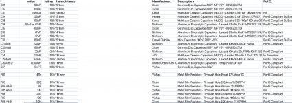
I have not made the part list...was Byron that collected some informs
and produced the part lists.
You can use higher voltage if you want...some guys believe this is more safe.
I am saying.... and sorry to be so late...that 63 volts, to the supply electrolitic condensers and on board supply condensers is good.
Also i said that 80 volts and 100 volts is overkill.... but does not cause any harm...if people is wealthy enough or if following the part lists...then go ahead..anything will explode..only your wallet.
My failure...yes.... i should have fixed...doing now...better late than never.
I am not perfect... Byron or the guy that suggested him 100 volts is not perfect too... this happens.
regards,
Carlos
Carlos, for tweaking the gain, before tampering with the 390 ohms resistor, what is the actual sensivity of the input?
What maximum RMS voltage will give the full power before clipping?
Thanks,
Martin.
What maximum RMS voltage will give the full power before clipping?
Thanks,
Martin.
I will not enter this level of details my dear Cannonica
Your questions have multiple answers as each value will have a result..i will need to produce a chart and i really do not want to do that and my free time these days does not allow me to go to this level of details.
Install a trimpot and adjust the way you feel better.
regards,
Carlos
Your questions have multiple answers as each value will have a result..i will need to produce a chart and i really do not want to do that and my free time these days does not allow me to go to this level of details.
Install a trimpot and adjust the way you feel better.
regards,
Carlos
Wich should I choose?Per channel I've 5 pieces of MJW3281A and 5 MJW1302A trannies or 4 pieces of MJL4281A and MJL4302A.
I know the first one can't transfer as much heat like the MJL trannies cause they are smaller.
I know the first one can't transfer as much heat like the MJL trannies cause they are smaller.
- Status
- Not open for further replies.
- Home
- Amplifiers
- Solid State
- Dx Blame MKIII-Hx - Builder's thread